


OPERA
143
EN
cod. 3541R960 - Rev. 00 - 09/2019
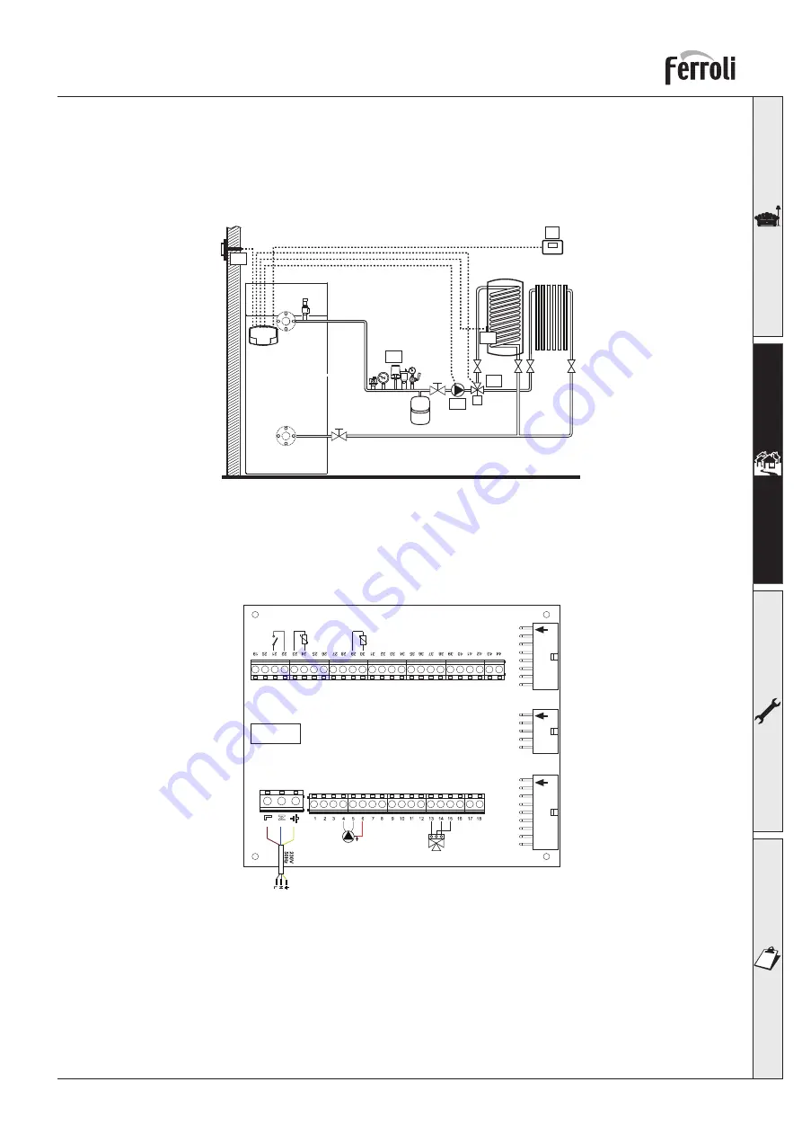
Two direct heating circuits
- Schematic diagram
fig. 35
- Electrical connections
After installation, carry out the necessary electrical connections as shown in the wiring diagram.
Then configure the controller as described in the specific section.
fig. 36
Legend
72
1st zone (direct) room thermostat
72b
2nd zone (direct) room thermostat
138
External probe
307
1st zone (direct) circulating pump
306
2nd zone (direct) circulating pump
a
1st zone (direct)
b
2nd zone (direct)
M
Delivery
R
Return
I*
ISPESL safety devices (when required - not su-
pplied)
To manage the sliding temperature it is necessary
to purchase the external probe accessory code
013018X0
29
FORCE W
154
RO
Un circuit de înc
ă
lzire direct
ú
i un circuit de ap
ă
menajer
ă
cu valv
ă
deviatoare (cu 3 fire)
- Schem
ă
de principiu
Utiliza
Ġ
i valve deviatoare cu 3 fire: FAZA DE DESCHIDERE 230 V - FAZA DE ÎNCHIDERE 230 V - NEUTRU
cu timpi de comutare (de la complet închis la complet deschis) nu mai mari de 90 secunde.
fig. 45
- Conexiuni electrice
Dup
ă
instalare va fi necesar s
ă
se efectueze conexiunile electrice necesare, a
ú
a cum se arat
ă
în schema electric
ă
.
Dup
ă
aceea, trece
Ġ
i la configurarea unit
ăĠ
ii de comand
ă
, dup
ă
cum se arat
ă
în paragraful respectiv.
fig. 46
Legend
ă
32
Pomp
ă
de circula
Ġ
ie înc
ă
lzire
a
Zona 1 (direct
ă
)
72
Termostat de camer
ă
zona 1 (direct
ă
)
b
Circuit boiler
138
Sond
ă
extern
ă
M
Tur
155
Sond
ă
boiler
R
Retur
348
Valv
ă
cu 3 c
ă
i (cu trei fire)
A =
FAZA DE DESCHIDERE
B =
NEUTRU
C =
FAZA DE ÎNCHIDERE
I*
Dispozitive de siguran
Ġă
ISPESL (Când sunt necesare - nu sunt furnizate)
cod. 3541Q762 - Rev. 00 - 05/2019
OPERA
147
EN
cod. 3541R960 - Rev. 00 - 09/2019
A direct heating circuit and a DHW circuit with diverter valve (3-wire)
- Schematic diagram
Use diverter valves with 3 wires:
- 230V OPENING PHASE
- 230V CLOSING PHASE
- NEUTRAL
with switching times (from all closed to all open) of not more than 90 seconds.
fig. 41
- Electrical connections
After installation, carry out the necessary electrical connections as shown in the wiring diagram.
Then configure the controller as described in the specific section.
fig. 42
OPERA
147
EN
cod.
3
541R96
0
- Rev. 00
- 09/
201
9
A
dir
ect
h
eat
ing
circu
it and
a
DHW
ci
rc
uit
with
d
ive
rt
er
va
lv
e
(3
-wir
e)
- Sc
he
ma
tic
d
ia
gram
Use di
ve
rte
r val
ve
s wi
th
3 wi
re
s:
- 230V OPENING
PH
ASE
- 2
30
V C
LO
S
IN
G
P
H
AS
E
- NEUTRAL
with switchin
g ti
me
s (from
all closed
to
all
o
pen)
of
no
t more
than
9
0 se
cond
s.
fig
.41
- Elec
trica
l co
nne
ction
s
Afte
r in
stal
lation
, carry
ou
t the
ne
cessary
electric
al conn
ections as shown
in
the
w
iring
di
agram.
Then con
fig
ure th
e controlle
r a
s de
scri
bed in
the
spe
cifi
c section
.
fig
.42


