


27
DOMITOP HF 24 - 30 E
FERELLA GOLD HF 24 - 30 MEL
Version - 09.2002
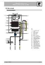
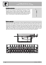
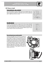
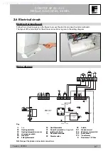
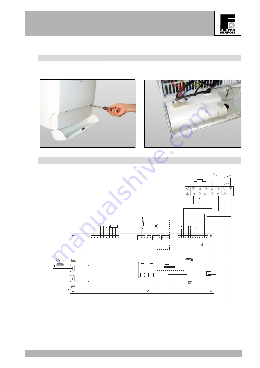
2.6 Electrical circuit
Electrical terminal board
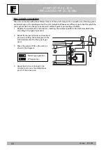
Follow the instructions given in the figure to access the electrical connection terminal board.
The layout of the terminals for the various connections is given in the wiring diagram.
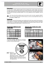
Wiring diagram
X6
X1
X2
X3
X4
1
2
1
2
1
3
1
2
3
4
5
6
7
8
9
10
1
2
3
4
5
6
7
8
9
10
11
12
13
2
1
X5
TEST
X12
1
2
1
2
3
4
5
6
7
8
9
X10
W
O
V
R
X8
X7
81
82
PMF03F
JP02
JP01
JP03
Nat/LPG
X11
230V
24V
230V
24V
BR
Blue
BR
Blue
BR
Blue
MV1
MV2
MV3
MV4
Blue
BR
Blue
BR
BR
Blue
R
R
O
O
Blue
BR
BL
BL
X9
1
2
3
Blue
BR
W
W
101
L
N
8
7
6
5
4
3
2
1
95
155
BL
BL
Y/G
Y/G
R
98
50
114
34
32
44
49
16
43
175
72
Key
16
Fan
32
Heating circulator
34
Heating temperature sensor
43
Air pressure switch
44
Gas valve
49
Safety thermostat
98
Switch
101
Electronic card
114
Water pressure switch
155
Boiler sensor
175
Transformer
R
Resistance 1.8 Ohm
50
Limit thermostat
72
Room thermostat
(not supplied)
81
Ignition electrode
82
Detection electrode
95
Diverter valve
N.B. Respect the phase and neutral connections
Supplied by HeatingSpares247.com


