


15
DOMITOP HF 24 - 30 E
FERELLA GOLD HF 24 - 30 MEL
Version - 09.2002
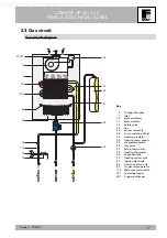
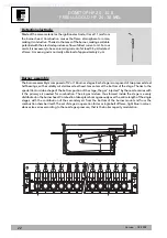
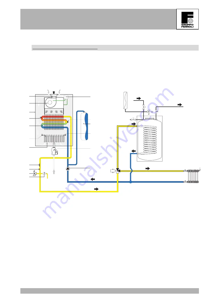
2.2 Hydraulic circuit - tap water via external boiler
Hydraulic diagram for tap water
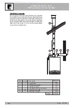
The HF is a boiler for heating only. However, if required, the HF has a special kit for connecting the boiler
for tap water, too, via an external boiler. The solution shown in the hydraulic diagram has a three-way diverter
valve and a sensor for the external boiler. The kits also contain connection pipes that vary depending on the
model. The tap water temperature can be adjusted by inserting the knob (included in the kit) in the control
panel (D).
43
49
50
56
81
44
32
20
82
222
5
29-187
16
74
14
114
34
7
- +
10
11
VD
B
E
D
C
F
A
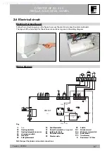
Key
5
Airtight chamber
7
Inlet
1 0
System delivery
1 1
System return
1 4
Safety valve
1 6
Fan
2 0
Burner assembly
2 9
Fume outlet manifold
3 2
Heating circulator
3 4
Heating temp. sensor
4 3
Air pressure switch
4 4
Gas valve
4 9
Safety thermostat
5 0
Heating thermostat
5 6
Expansion tank
7 4
Heating system cock
8 1
Ignition electrode
8 2
Detection electrode
8 4
1st gas valve operator
1 1 4
Water pressure switch
1 8 7
Fume diaphragm
A
Boiler
B
External boiler
C
Boiler expansion tank
D
Tap water inlet
E
Tap water outlet
F
Heating circuit
Supplied by HeatingSpares247.com


