background image

ATLAS D 30 PLUS UNIT

42

EN

cod. 3540U263  -  06/2012  (Rev. 00)

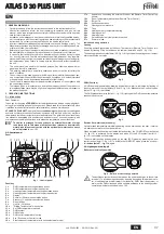
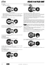
Pump pressure adjustment

The pump pressure is factory set for optimum operation and should not normally be
changed. However, if special needs require a different pressure, after applying the pres-
sure gauge and lighting the burner turn the adjustment screw "6" indicated in fig. 142. In
any case, make sure to keep within the range of 10 - 14 bar.

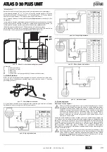
fig. 25 - SUNTEC pump

fig. 26 - DANFOSS pump

1.

Inlet (suction)

2.

Return with internal bypass grub screw

3.

Outlet to nozzle

4.

Pressure gauge connection

5.

Vacuum gauge connection

6.

Adjustment screw

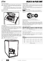
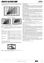
Head and air shutter

Adjust the head and air flow rate according to the burner power as indicated in fig. 144
Turn the head adjustment screw 

(fig. 145) clockwise or anticlockwise until the mark on

rod 

A

 (fig. 145) coincides with the pointer.

fig. 27 - Burner adjustments graph SUN G6R

A

Power

B

Adjustment pointer

C

Oil flow rate
"L" head (mm)
Air

To adjust the air flow, turn screw 

C

 (fig. 145) after loosening nut 

D

. After making the ad-

justment, tighten nut 

D

.

fig. 28 - Burner adjustment

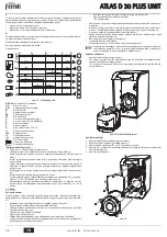
Position of electrodes - baffle

After fitting the nozzle, check correct positioning of the electrodes and baffle, according
to the values given below. It is advisable to check the values after every operation on the
head.

fig. 29 - Electrode - baffle position

4.2 Commissioning

B

Checks to be made at first lighting, and after all maintenance operations involving dis-
connection from the systems or an operation on safety devices or parts of the boiler:

Before lighting the boiler

Open any on-off valves between the boiler and the systems.

Check the tightness of the fuel system.

Check the pre-filling of the expansion tank 

Fill the water system and make sure that all air contained in the boiler and the system has
been vented by opening the air vent valve on the boiler and any vent valves on the system.

Make sure there are no water leaks in the system, hot water circuits, connections or boiler.

Make sure the electrical system is properly connected and the earth system works properly.

Make sure there are no flammable liquids or materials in the immediate vicinity of the boiler.

Fit the pressure gauge and the vacuum gauge on the pump (remove after starting) of the
burner.

open the gate valves along the diesel pipe

Start-up

fig. 30 - Starting

m h

2

O

PV

1

2

3

6

5

4

1

2

4

5

3

6

30

25

20

15

10

5

0

B

15.0

20.0

25.0

30.0

35.0

40.0

45.0

50.0

55.0

60.0

A (kW)

1,26

1,69

2,11

2,53

2,95

3,37

3,79

4,22

4,64

5,06

C (kg/h)

45.0°

6.5

3.5

3

1

L

VE

G

P

VE

G

P

A

B

Summary of Contents for ATLAS D 30 PLUS UNIT

Page 1: ...NSTALACIÓN Y MANTENIMIENTO TR KULLANMA KURULUM VE BAKøM TALIMATLARø EN INSTRUCTIONS FOR USE INSTALLATION AND MAINTENANCE FR INSTRUCTIONS D UTILISATION D INSTALLATION ET D ENTRETIEN GR ȅǻǾīǴǼȈ ȋȇdzȈǾȈ ǼīȀǹȉDZȈȉǹȈǾȈ Ȁǹǿ ȈȊȃȉdzȇǾȈǾȈ NL AANWIJZINGEN VOOR GEBRUIK INSTALLATIE EN ONDERHOUD RU ɊɍɄɈȼɈȾɋɌȼɈ ɉɈ ɗɄɋɉɅɍȺɌȺɐɂɂ ɆɈɇɌȺɀɍ ɂ ɌȿɏɈȻɋɅɍɀɂȼȺɇɂɘ ...

Page 2: ...l collegamento ad un bollitore esterno per acqua calda sanitaria opzionale In questo manuale tutte le funzioni re lative la produzione di acqua calda sanitaria sono attive solo con bollitore sanitario opzionale collegato come indicato alla sez 3 3 2 2 Pannello comandi Pannello fig 1 Pannello di controllo Legenda pannello 1 Tasto decremento impostazione temperatura acqua calda sanitaria 2 Tasto inc...

Page 3: ...mbiente con cronocomando remoto opzionale Impostare tramite il cronocomando remoto la temperatura ambiente desiderata all inter no dei locali La caldaia regolerà l acqua impianto in funzione della temperatura ambien te richiesta Per quanto riguarda il funzionamento con cronocomando remoto fare riferimento al relativo manuale d uso Temperatura scorrevole Quando viene installata la sonda esterna opz...

Page 4: ... tubazioni dell impianto per rimuovere residui o impurità che potrebbero compromettere il buon funzionamento dell apparecchio Effettuare gli allacciamenti ai corrispettivi attacchi secondo il disegno riportato al cap 5 ed ai simboli riportati sull apparecchio Caratteristiche dell acqua impianto In presenza di acqua con durezza superiore ai 25 Fr 1 F 10ppm CaCO3 si prescrive l uso di acqua opportun...

Page 5: ...di tubazioni LMAX riportate in tabella fig 18 Alimentazione per gravità fig 19 Alimentazione per aspirazione fig 20 Alimentazione a sifone fig 21 Alimentazione ad anello 3 5 Collegamenti elettrici Collegamento alla rete elettrica B La sicurezza elettrica dell apparecchio è raggiunta soltanto quando lo stesso è correttamente collegato ad un efficace impianto di messa a terra eseguito come previsto ...

Page 6: ...d acqua Verificare periodicamente la presenza di acqua nel sifone fig 23 Scarico condensa 4 SERVIZIO E MANUTENZIONE Tutte le operazioni di regolazione trasformazione messa in servizio manutenzione de scritte di seguito devono essere effettuate solo da Personale Qualificato e di sicura qua lificazione in possesso dei requisiti tecnici professionali previsti dalla normativa vigente come il personale...

Page 7: ...lettrodi e deflettore secondo le quote sottoindicate E opportuno eseguire una verifica delle quote dopo ogni intervento sulla testa fig 29 Posizione elettrodi deflettore 4 2 Messa in servizio B Verifiche da eseguire alla prima accensione e dopo tutte le operazioni di ma nutenzione che abbiano comportato la disconnessione dagli impianti o un inter vento su organi di sicurezza o parti della caldaia ...

Page 8: ...a temperature ecc 4 3 Manutenzione Controllo periodico Per mantenere nel tempo il corretto funzionamento dell apparecchio è necessario far eseguire da personale qualificato un controllo annuale che preveda le seguenti verifiche I dispositivi di comando e di sicurezza devono funzionare correttamente Il circuito di evacuazione fumi deve essere in perfetta efficienza Controllare che non ci siano even...

Page 9: ...fettosi o a massa Sostituire Cavi elettrodi deformati da alta tempera tura Sostituire e proteggere Collegamenti elettrici valvola o trasforma tore errati Controllare Giunto motore pompa rotto Sostituire Aspirazione pompa collegata al tubo di ritorno Correggere collegamento Fotoresistenza difettosa Sostituire Fotoresistenza sporca Pulire foto resistenza A02 Segnale fiamma pre sente con bruciatore s...

Page 10: ...ata impianto 3 4 a2 Ritorno impianto 1 a3 Scarico 1 2 a4 Camino Ø 110 a6 Scarico condensa 14 Valvola di sicurezza riscaldamento 32 Circolatore riscaldamento 36 Sfiato aria automatico 56 Vaso espansione 246 Trasduttore di pressione 278 Sensore doppio Sicurezza riscaldamento 295 Bruciatore 338 Recuperatore fumi 36 246 32 295 850 500 830 56 338 14 278 246 320 97 5 50 200 250 343 14 105 63 5 a4 a2 a3 ...

Page 11: ...mento 50 30 kW 17 P Rendimento Pmax 80 60 C 96 3 Rendimento Pmin 80 60 C 97 2 Rendimento Pmax 50 30 C 102 4 Rendimento Pmin 50 30 C 103 4 Rendimento 30 102 7 Classe efficienza direttiva 92 42 EEC Pressione max esercizio riscaldamento bar 3 PMS Pressione min esercizio riscaldamento bar 0 8 Temperatura max riscaldamento C 95 tmax Contenuto acqua riscaldamento litri 21 Grado protezione IP X0D Tension...

Page 12: ...ata 230 Vac Posizione riscaldamento Non Alimentata Posizione sanitario 138 Sonda esterna opzionale 139 Unità ambiente opzionale 246 Trasduttore di pressione 278 Sensore doppio Sicurezza riscaldamento TR Trasformatore d accensione PR Preriscaldatore FR Fotoresistenza MB Motore bruciatore VE Valvola elettromagnetica DBM06C T T 278 OUT 5V GND 246 DSP05 L N 4 5 6 7 8 9 10 11 12 13 14 15 16 17 18 L N 2...

Page 13: ...n effettuato a cura dell azienda inosservanza delle istruzioni e delle avvertenze previste dall azienda produttrice e riportate sui manuali di utilizzo a corredo del prodotto errata installazione o inosservanza delle prescrizioni di installazione previste dall azienda produttrice e riportate sui manuali di installazione a corredo del prodotto inosservanza di norme e o disposizioni previste da legg...

Page 14: ...do como se indica en sec 8 3 2 2 Panel de mandos Panel fig 1 Panel de control Leyenda del panel 1 Tecla para disminuir la temperatura del ACS 2 Tecla para aumentar la temperatura del ACS 3 Tecla para disminuir la temperatura de calefacción 4 Tecla para aumentar la temperatura de calefacción 5 Pantalla 6 Tecla de selección del modo Verano Invierno 7 Tecla de selección del modo Economy Comfort 8 Tec...

Page 15: ...ción de la temperatura ambiente con el reloj programador a distancia op cional Mediante el reloj programador a distancia establecer la temperatura ambiente deseada en el interior de la vivienda La caldera regula el agua de la calefacción en función de la temperatura ambiente requerida Por lo que se refiere al funcionamiento con el reloj pro gramador a distancia consultar su manual de uso Temperatu...

Page 16: ...lación para eliminar los residuos o impurezas ya que podrían comprometer el funcionamiento co rrecto del aparato Efectuar las conexiones de acuerdo con el dibujo del cap 10 y los símbolos presentes en el aparato Características del agua de la instalación En presencia de agua de dureza superior a 25 Fr 1 F 10 ppm CaCO3 es necesario usar agua adecuadamente tratada a fin de evitar posibles incrustaci...

Page 17: ...e los siguientes es quemas sin superar las longitudes LMAX de las tuberías que se indican en la tabla fig 18 Alimentación por gravedad fig 19 Alimentación por aspiración fig 20 Alimentación con sifón fig 21 Alimentación en anillo 3 5 Conexiones eléctricas Conexión a la red eléctrica B La seguridad eléctrica del aparato sólo se logra cuando éste se encuentra co nectado a una toma de tierra eficaz s...

Page 18: ...amente el nivel de agua en el sifón fig 23 Drenaje de condensados 4 SERVICIO Y MANTENIMIENTO Todas las operaciones de regulación transformación puesta en servicio y manteni miento que se describen a continuación deben ser efectuadas exclusivamente por un técnico matriculado por ejemplo del Servicio de Asistencia local FERROLI declina toda responsabilidad por daños materiales o personales provocado...

Page 19: ... los electrodos y del deflector se gún las cotas indicadas a continuación Es necesario efectuar un control de las cotas después de cada intervención en el cabezal fig 29 Posición de los electrodos y del deflector 4 2 Puesta en servicio B Controles que se han de efectuar durante el primer encendido tras las opera ciones de mantenimiento que exijan desconectar la caldera y después de toda intervenci...

Page 20: ...tes que pue dan requerirse curva de compensación potencia temperaturas etc 4 3 Mantenimiento Control periódico Para que el aparato funcione correctamente es necesario que un técnico cualificado efectúe una revisión anual a fin de Comprobar el funcionamiento correcto de los dispositivos de mando y seguridad Comprobar la eficacia de la tubería de salida de humos Controlar que no haya obstrucciones o...

Page 21: ...deformados por alta temperatura Cambiar y proteger Conexiones eléctricas incorrectas de vál vula o transformador Controlar Acoplamiento motor bomba roto Cambiar Aspiración de la bomba conectada al tubo de retorno Corregir la conexión Fotorresistencia defectuosa Cambiar Fotorresistencia sucia Limpiar la fotorresistencia A02 Señal de llama pre sente con quemador apagado Fotorresistencia en cortocirc...

Page 22: ... 3 4 a2 Retorno instalación 1 a3 Salida de humos 1 2 a4 Chimenea Ø 110 a6 Drenaje de condensados 14 Válvula de seguridad calefacción 32 Bomba de circulación calefacción 36 Purgador de aire automático 56 Vaso de expansión 246 Transductor de presión 278 Sensor doble seguridad calefacción 295 Quemador 338 Recuperador de humos 36 246 32 295 850 500 830 56 338 14 278 246 320 97 5 50 200 250 343 14 105 ...

Page 23: ...ión 50 30 C kW 17 P Rendimiento Pmáx 80 60 C 96 3 Rendimiento Pmín 80 60 C 97 2 Rendimiento Pmáx 50 30 C 102 4 Rendimiento Pmín 50 30 C 103 4 Rendimiento 30 102 7 Clase de eficiencia según directiva 92 42 CE Presión máxima funcionamiento calefacción bar 3 PMS Presión mínima funcionamiento calefacción bar 0 8 Temperatura máxima agua calefacción C 95 tmáx Contenido circuito de calefacción litros 21 ...

Page 24: ... Alimentada 230 Vca posición de calefacción No alimentada posición ACS 138 Sonda exterior opcional 139 Unidad de ambiente opcional 246 Transductor de presión 278 Sensor doble seguridad calefacción TR Transformador de encendido PR Precalentador FR Fotorresistencia MB Motor quemador VE Válvula electromagnética DBM06C T T 278 OUT 5V GND 246 DSP05 L N 4 5 6 7 8 9 10 11 12 13 14 15 16 17 18 L N 230V 50...

Page 25: ...in cargo de los componentes siendo por cuenta del usuario la mano de obra y el desplazamiento Cuerpo de las calderas de chapa Un año Cuerpo de las calderas de hierro fundido Un año cada elemento Cuerpo de cobre de las calderas murales Un año Acumuladores de los grupos térmicos montados en calderas Tres años Esta garantía comercial es válida siempre que se realicen las operaciones normales de mante...

Page 26: ...i için harici bir ÕsÕtÕcÕ kazana ba lanmak üzere tasarlanmÕútÕr opsiyonel Bu kullanÕm kÕlavuzundaki sÕcak musluk suyu üretimiyle ilgili fonksiyonlarÕn tümü sadece opsiyonel sÕcak su ÕsÕtma kazanÕnÕn ba lanmasÕ durumunda aktif hale gelir ba lantÕ úekli aúa Õdaki bölümlerde belirtildi i gibidir sez 3 3 2 2 Komut paneli Panel úek 1 Kontrol paneli Panel açÕklamalarÕ 1 SÕcak sÕhhi su sÕcaklÕk ayarÕnÕ a...

Page 27: ...dalÕ zamanlayÕcÕ ile Uzaktan kumandalÕ zamanlayÕcÕ kontrolünü kullanarak sÕcaklÕk de erini oda için istenen de ere ayarlayÕnÕz Kombi ünitesi sistem suyunu istenilen ortam sÕcaklÕ Õ de erine göre ayarlayacaktÕr Uzaktan kumandalÕ zamanlayÕcÕ kontrolü ile ilgili daha fazla bilgi için lütfen bu cihazÕn kullanÕcÕ kitabÕna bakÕnÕz SÕcaklÕk akÕúÕ Harici sensörün monte edilmesi opsiyonel ile kumanda panel...

Page 28: ...esisatÕn bütün borularÕnÕ dikkatli bir úekilde yÕkayÕnÕz Ba lantÕlarÕ ilgili ba lantÕ noktalarÕna cap 5 kÕsmÕnda belirtildi i gibi ve cihaz üzerinde belirtilen sembollere riayet ederek yapÕnÕz Sistem suyunun özellikleri Suyun 25 Fr sertlik derecesinden 1 F 10ppm CaCO3 daha sert olmasÕ halinde kom bide sert suyun sebep oldu u kireç oluúumlarÕnÕ önlemek amacÕyla uygun su kullanÕmÕnÕ öneririz Ancak y...

Page 29: ...aúmamalÕdÕr úek 18 A ÕrlÕ Õ ile besleme úek 19 Emiú yoluyla besleme úek 20 Sifon yöntemiyle besleme úek 21 Halka beslemesi 3 5 Elektrik ba lantÕlarÕ Elektrik úebekesine ba lantÕ B CihazÕn elektriksel güvenli i sadece e er mevcut standartlara uygun bir úekil de verimli ve etkin topraklama sistemine do ru bir úekilde ba lanÕrsa garanti edilmektedir Mesleki açÕdan kalifiye bir personele topraklama si...

Page 30: ...ediniz úek 23 Yo uúma tahliyesi 4 SERVIS VE BAKøM AçÕklanan tüm ayarlama ve dönüútürme servise alma bakÕm iúlemleri sadece Kalifiye bir Personel yürürlükteki standartlarÕn öngördü ü profesyonel teknik gereklilikler hakkÕnda bilgi sahibi olan bir personel veya Müúteri Teknik Destek Servisinden gelen personeller tarafÕndan gerçekleútirilmelidir FERROLI cihazÕn yetkisiz kiúiler tarafÕndan kurcalanmas...

Page 31: ...n uzaklÕklara göre elektrotlarÕn ve deflektörün do ru konumlarÕnda olup olmadÕ ÕnÕ kontrol ediniz BaúlÕk kafa üzerinde he rhangi bir çalÕúma yapÕldÕktan sonra uzaklÕklar kontrol edilmelidir úek 29 Elektrot deflektör saptÕrÕcÕ konumu 4 2 Servise alma B ølk çalÕútÕrma anÕnda ve sistemden ba lantÕnÕn kesilmesi veya emniyet cihaz larÕnda ya da kombinin di er aksamlarÕnda bir bakÕm iúleminin de dahil o...

Page 32: ... 4 3 BakÕm Periyodik kontrol CihazÕn zaman içinde düzgün bir úekilde çalÕúmaya devam etmesini sa lamak için aúa Õdaki kontrol iúlemlerini yÕllÕk olarak kalifiye bir personele yaptÕrmanÕz gerekmekte dir Kumanda ve emniyet cihazlarÕ do ru bir úekilde çalÕúÕyor olmalÕdÕr Duman tahliye devresi mükemmel verimlilikte olmalÕdÕr YakÕt besleme ve geri dönüú borularÕnda hiç bir engelleme tÕkanÕklÕk ya da gö...

Page 33: ... olmuú De iútiriniz ve koruyunuz Valf ya da transformatör elektrik ba lantÕlarÕ hatalÕ Kontrol ediniz Motor pompa ba lantÕsÕ kÕrÕk De iútiriniz Pompa giriúi giriú borusuna ba lanmÕú Ba lantÕyÕ düzeltiniz Foto rezistans kusurlu De iútiriniz Foto rezistans kirli Foto rezistansÕ temizleyiniz A02 Brülör kapalÕ iken alev sinyali var Foto rezistans kÕsa devre Foto rezistansÕ de iútiriniz Harici ÕúÕk fot...

Page 34: ...kadan görünüm a1 Sistem çÕkÕúÕ 3 4 a2 Sistem giriúi 1 a3 Tahliye 1 2 a4 Baca Ø 110 a6 Yo uúma tahliyesi 14 IsÕtma emniyet valfÕ 32 IsÕtma sirkülatörü 36 Otomatik hava tahliyesi 56 Genleúme tankÕ 246 BasÕnç düúürücü 278 Çift sensör Emniyet IsÕtma 295 Brülör 338 Duman de iútirgeci 36 246 32 295 850 500 830 56 338 14 278 246 320 97 5 50 200 250 343 14 105 63 5 a4 a2 a3 a1 418 717 a6 ...

Page 35: ...31 8 P IsÕtma min termik gücü 50 30 C kW 17 P Verim Pmax 80 60 C 96 3 Verim Pmin 80 60 C 97 2 Verim Pmax 50 30 C 102 4 Verim Pmin 50 30 C 103 4 Verim 30 102 7 92 42 EEC Direktifi verim sÕnÕfÕ IsÕtmada maksimum çalÕúma basÕncÕ bar 3 PMS IsÕtmada minimum çalÕúma basÕncÕ bar 0 8 IsÕtma maks sÕcaklÕ Õ C 95 tmax IsÕtma suyu kapasitesi litre 21 Koruma derecesi IP X0D Besleme gerilimi V Hz 230 50 Çekilen...

Page 36: ...sleme verildi inde 230 Vac IsÕtma konumu Besleme verilmedi inde SÕhhi su konumu 138 Harici sensör opsiyonel 139 Ortam ünitesi opsiyonel 246 BasÕnç dönüútürücüsü 278 Çift sensör Emniyet ÕsÕtma TR Ateúleme transformatörü PR Ön ÕsÕtÕcÕ FR Foto rezistans MB Brülör motoru VE Elektromanyetik valf DBM06C T T 278 OUT 5V GND 246 DSP05 L N 4 5 6 7 8 9 10 11 12 13 14 15 16 17 18 L N 230V 50Hz 32 138 139 72 T...

Page 37: ...on to an external hot water storage tank optional In this manual all the functions relevant to domestic hot water production are only active with the optional hot water tank connect ed as indicated in sec 18 3 2 2 Control panel Panel fig 1 Control panel Panel key 1 DHW temperature setting decrease button 2 DHW temperature setting increase button 3 Heating system temperature setting decrease button...

Page 38: ...m temperature adjustment with optional remote timer control Using the remote timer control set the temperature desired in the rooms The boiler unit will set the system water according to the required room temperature For information on the remote timer control please refer to its user s manual Sliding temperature When the optional external probe is installed the control panel display detail 5 fig ...

Page 39: ...any residuals or impurities that could affect proper operation of the unit Carry out the relevant connections according to the diagram in cap 20 and the symbols given on the unit Water system characteristics In the presence of water harder than 25 Fr 1 F 10ppm CaCO3 use suitably treated water in order to avoid possible scaling in the boiler Treatment must not reduce the hard ness to values below 1...

Page 40: ...ing the pipe lengths LMAX given in the table fig 18 Gravity feed fig 19 Suction feed fig 20 Siphon feed fig 21 Ring feed 3 5 Electrical connections Connection to the electrical grid B The unit s electrical safety is only guaranteed when correctly connected to an efficient earthing system executed according to current safety standards Have the efficiency and suitability of the earthing system check...

Page 41: ...he trap before starting the unit Periodically check the water in the trap fig 23 Condensate drain 4 SERVICE AND MAINTENANCE All adjustment conversion startup and maintenance operations described below must only be carried out by Qualified Personnel meeting the professional technical require ments prescribed by current regulations such as those of the Local After Sales Techni cal Service FERROLI de...

Page 42: ...lectrodes and baffle according to the values given below It is advisable to check the values after every operation on the head fig 29 Electrode baffle position 4 2 Commissioning B Checks to be made at first lighting and after all maintenance operations involving dis connection from the systems or an operation on safety devices or parts of the boiler Before lighting the boiler Open any on off valve...

Page 43: ...tom ization compensation curve power temperatures etc 4 3 Maintenance Periodical check To ensure correct operation of the unit over time have qualified personnel carry out a yearly check providing for the following The control and safety devices must function correctly The fume exhaust circuit must be perfectly efficient Check there are no obstructions or dents in the fuel supply and return pipes ...

Page 44: ...rode wires or earthed Replace Electrode wires deformed by high tem perature Replace and protect Faulty valve or transformer electrical con nections Check Broken pump motor joint Replace Pump inlet connected to return pipe Correct the connection Faulty photoresistance Replace Dirty photoresistance Clean the photoresistance A02 Flame present signal with burner off Photoresistance short circuit Repla...

Page 45: ...Rear View a1 System delivery 3 4 a2 System return 1 a3 Outlet 1 2 a4 Flue Ø 110 a6 Condensate drain 14 Heating safety valve 32 Heating circulating pump 36 Automatic air vent 56 Expansion tank 246 Pressure transducer 278 Double sensor Safety Heating 295 Burner 338 Fume recuperator 36 246 32 295 850 500 830 56 338 14 278 246 320 97 5 50 200 250 343 14 105 63 5 a4 a2 a3 a1 418 717 a6 ...

Page 46: ...in heating 50 30 kW 17 P Efficiency Pmax 80 60 C 96 3 Efficiency Pmin 80 60 C 97 2 Efficiency Pmax 50 30 C 102 4 Efficiency Pmin 50 30 C 103 4 Efficiency 30 102 7 Efficiency class Directive 92 42 EEC Max working pressure in heating bar 3 PMS Min working pressure in heating bar 0 8 Max heating temperature C 95 tmax Heating water content litres 21 Protection rating IP X0D Power supply voltage V Hz 2...

Page 47: ...lve optional Fed 230 Vac Heating position Not Fed DHW position 138 External probe optional 139 Room unit optional 246 Pressure transducer 278 Double sensor Safety Heating TR Ignition transformer PR Preheater FR Photoresistance MB Burner motor VE Electromagnetic valve DBM06C T T 278 OUT 5V GND 246 DSP05 L N 4 5 6 7 8 9 10 11 12 13 14 15 16 17 18 L N 230V 50Hz 32 138 139 72 TR MB 1 M PR Tm VE FR 95 ...

Page 48: ...nt à la production d eau chaude sanitaire op tion peut être raccordé à la chaudière Dans ce manuel toutes les fonc tions relatives à la production d eau chaude sanitaire sont actives uniquement avec le ballon sanitaire optionnel comme indiqué au sez 23 3 2 2 Tableau des commandes Panneau fig 1 Panneau de contrôle Légende panneau 1 Touche pour réduire la température de l eau chaude sanitaire 2 Touc...

Page 49: ...de la température ambiante par chronocommande à distance en op tion Programmer à l aide de la chronocommande à distance la température souhaitée à l in térieur des pièces La chaudière réglera la température dans le circuit d eau de l instal lation en fonction de la température ambiante demandée Pour le fonctionnement par chronocommande à distance se reporter au manuel d utilisation spécifique Temp...

Page 50: ... prévus comme indiqué au chapitre cap 25 et conformément aux plaques des pictogrammes apposées sur l appareil Caractéristiques de l eau de l installation En présence d une eau ayant un degré de dureté supérieur à 25 Fr 1 F 10ppm CaCO3 il est recommandé d utiliser une eau spécialement traitée afin d éviter toute in crustation éventuelle dans la chaudière Le traitement ne doit pas réduire la dureté ...

Page 51: ...eau fig 18 Alimentation par gravité fig 19 Alimentation par aspiration fig 20 Alimentation par syphon fig 21 Alimentation par anneau 3 5 Branchements électriques Raccordement au réseau électrique B La sécurité électrique de l appareil ne peut être assurée que lorsque celui ci est correctement raccordé à un dispositif de mise à la terre efficace conformément aux normes électriques en vigueur Faire ...

Page 52: ...s 4 UTILISATION ET ENTRETIEN Toutes les opérations de réglage de transformation de mise en service et d entretien décrites ci après doivent être effectuées par un professionnel qualifié conformément aux textes réglementaires et aux règles de l art en vigueur par exemple le personnel SAT le plus proche FERROLI Toute responsabilité contractuelle et extracontractuelle du constructeur est exclue pour ...

Page 53: ...éflecteur Après avoir monté le gicleur vérifier le positionnement correct des électrodes et des dé flecteurs selon les cotes indiquées Procéder à une vérification des cotes après chaque intervention sur la tête fig 29 Position des électrodes déflecteur 4 2 Mise en service B Vérifications à effectuer au premier allumage et après toutes les opérations d entretien ayant occasionné des débranchements ...

Page 54: ...Pour un fonctionnement correct durable de l appareil il est nécessaire de faire effectuer par un professionnel qualifié un contrôle annuel qui prévoit les opérations suivantes Les dispositifs de commande et de sécurité doivent fonctionner correctement Le circuit d évacuation des fumées doit être parfaitement efficace S assurer que les tuyauteries d alimentation et de retour du combustible ne sont ...

Page 55: ...Câbles électrodes défectueux ou à la masse Remplacer Câbles électrodes déformés par la haute température Remplacer et protéger Faux raccordements électriques vanne ou transformateur Vérifier Joint moteur pompe cassé Remplacer Aspiration pompe reliée à la tuyauterie de retour Corriger le branchement Cellule photorésistante défectueuse Remplacer Cellule photorésistante sale Nettoyer la cellule photo...

Page 56: ...llation 3 4 a2 Retour installation 1 a3 Vidange 1 2 a4 Cheminée Ø 110 a6 Évacuation des condensats 14 Soupape de sûreté circuit chauffage 32 Circulateur circuit chauffage 36 Purgeur air automatique 56 Vase d expansion 246 Transducteur de pression 278 Capteur double sécurité chauffage 295 Brûleur 338 Récupérateur des fumées 36 246 32 295 850 500 830 56 338 14 278 246 320 97 5 50 200 250 343 14 105 ...

Page 57: ...chauffage 50 30 kW 17 P Rendement Pmax 80 60 C 96 3 Rendement Pmin 80 60 C 97 2 Rendement Pmax 50 30 C 102 4 Rendement Pmin 50 30 C 103 4 Rendement 30 102 7 Classe de rendement selon la directive européenne 92 42 EEC Pression maxi d utilisation chauffage bar 3 PMS Pression mini d utilisation chauffage bar 0 8 Température maxi chauffage C 95 tmax Capacité eau installation chauffage litres 21 Degré ...

Page 58: ...menté 230 Vca Position chauffage Non Alimenté Position sanitaire 138 Sonde extérieure option 139 Unité ambiante option 246 Transducteur de pression 278 Capteur double sécurité chauffage TR Transformateur d allumage PR Réchauffeur FR Cellule photorésistante MB Moteur brûleur VE Soupape électromagnétique DBM06C T T 278 OUT 5V GND 246 DSP05 L N 4 5 6 7 8 9 10 11 12 13 14 15 16 17 18 L N 230V 50Hz 32 ...

Page 59: ... 3ȓQDND9 FHLULVWKUȓZQ 3ȓQDND9 İȚț 1 3ȓQDND9 FHLULVWKUȓZQ SH ȒJKVK VXPEȩOZQ SȓQDND 1 RXPSȓ PHȓZVK9 UȪTPLVK9 THUPRNUDVȓD9 HVWRȪ QHURȪ RLNLDNȒ9 FUȒVK9 2 RXPSȓ DȪ KVK9 UȪTPLVK9 THUPRNUDVȓD9 HVWRȪ QHURȪ RLNLDNȒ9 FUȒVK9 3 RXPSȓ PHȓZVK9 UȪTPLVK9 THUPRNUDVȓD9 HJNDWȐVWDVK9 TȑUPDQVK9 4 RXPSȓ DȪ KVK9 UȪTPLVK9 THUPRNUDVȓD9 HJNDWȐVWDVK9 TȑUPDQVK9 5 2TȩQK 6 RXPSȓ HSLORJȒ9 THULQȒ9 FHLPHULQȒ9 OHLWRXUJȓD9 7 RXPSȓ ...

Page 60: ...ȐVWDVK VWKQ SURJUDPPDWLVPȑQK THUPRNUDVȓD NDWȐTOL K9 5ȪTPLVK WK9 THUPRNUDVȓD9 SHULEȐOORQWR9 PH SURDLUHWLNȩ H ZWHULNȩ FHLULVWȒULR SLOȑ WH PȑVZ WRX H ZWHULNRȪ FHLULVWKUȓRX WKQ HSLTXPKWȒ THUPRNUDVȓD SHULEȐOORQ WR9 VWR HVZWHULNȩ WZQ THUPDLQȩPHQZQ FȫUZQ 2 OȑEKWD9 UXTPȓ HL WR QHUȩ WK9 HJNDWȐ VWDVK9 DQDOȩJZ9 PH WKQ HSLTXPKWȒ THUPRNUDVȓD SHULEȐOORQWR9 LD WK OHLWRXUJȓD PH H ZWHULNȩ FHLULVWȒULR VXPERXOHXTHȓW...

Page 61: ... WR VFȑGLR VWK cap 30 NDL WD VȪPEROD SȐQZ VWK VXVNHXȒ DUDNWKULVWLNȐ WRX QHURȪ WK9 HJNDWȐVWDVK9 ȐQ K VNOKUȩWKWD WRX QHURȪ WK9 HJNDWȐVWDVK9 XSHUEDȓQHL WRX9 25 Fr 1 F 10ppm CaCO3 VXQLVWȐWDL K FUȒVK NDWȐOOKOD HSH HUJDVPȑQRX QHURȪ ȫVWH QD DSRIHȪJHWDL R SLTDQȩ9 VFKPDWLVPȩ9 DOȐWZQ VWR OȑEKWD HSH HUJDVȓD GH TD SUȑSHL QD PHLȫQHL WK VNOKUȩWKWD VH WLPȑ9 PLNUȩWHUH9 DSȩ 15 F 3 236 88 JLD FUȒVHL9 QHURȪ SUR9 ND ...

Page 62: ...UȐPPDWD WKUȫQWD9 WR PȒNR9 WZQ VZOKQȫVHZQ LMAX SRX DQDJUȐIH WDL VWRQ SȓQDND İȚț 18 7URIRGRVȓD PȑVZ EDUȪWKWD9 İȚț 19 7URIRGRVȓD PȑVZ DQDUUȩIKVK9 İȚț 20 7URIRGRVȓD PȑVZ VLIRQLRȪ İȚț 21 7URIRGRVȓD PȑVZ GDNWXOȓRX 3 5 OHNWULNȒ VXQGHVPRORJȓD 6ȪQGHVK VWR KOHNWULNȩ GȓNWXR B KOHNWULNȒ DVIȐOHLD WK9 VXVNHXȒ9 GLDVIDOȓ HWDL PȩQR ȩWDQ HȓQDL VZVWȐ VXQGHGHPȑQK VH DSRWHOHVPDWLNȒ HJNDWȐVWDVK JHȓZVK9 VȪPIZQD PH WRX9 ...

Page 63: ...Q XSȐUFHL QHUȩ VWR VLIȩQL İȚț 23 NNȑQZVK XJUDVȓD9 4 6ȑ5 9 6817Ȓ5 6 ǵOH9 RL HUJDVȓH9 UȪTPLVK9 PHWDWURSȒ9 OHLWRXUJȓD9 NDL VXQWȒUKVK9 SRX SHULJUȐIRQ WDL VWK VXQȑFHL SUȑSHL QD HNWHORȪQWDL PȩQR DSȩ H HLGLNHXPȑQR SURVZSLNȩ PH NDWȐO OKOK NDWȐUWLVK PH WL9 DSDUDȓWKWH9 HSDJJHOPDWLNȑ9 WHFQLNȑ9 JQȫVHL9 SRX RUȓ HL K LVFȪRXVD QRPRTHVȓD ȩSZ9 DSȩ WR SURVZSLNȩ WZQ WRSLNȫQ WPKPȐWZQ WHFQLNȒ9 XSRVWȒUL K9 SHODWȫQ FERR...

Page 64: ...9 DNȩORXTH9 DSRVWȐVHL9 ȓQDL VNȩSLPR QD JȓQH WDL ȑOHJFR9 WZQ DSRVWȐVHZQ PHWȐ DSȩ NȐTH HSȑPEDVK VWKQ NHIDOȒ İȚț 29 4ȑVK KOHNWURGȓZQ GLDIUȐJPDWR9 4 2 4ȑVK VH OHLWRXUJȓD B DzOHJFRL SRX SUȑSHL QD HNWHORȪQWDL NDWȐ WKQ SUȫWK HQHUJRSRȓKVK NDTȫ9 NDL PHWȐ DSȩ HUJDVȓH9 VXQWȒUKVK9 JLD WL9 RSRȓH9 DSDLWHȓWDL DSRVȪQGHVK WZQ VX VWKPȐWZQ Ȓ HSȑPEDVK VWD ȩUJDQD DVIDOHȓD9 Ȓ VWD H DUWȒPDWD WRX OȑEKWD 3ULQ DQȐ HWH WR Oȑ...

Page 65: ...URGR WRX FUȩQRX TD SUȑSHL QD DQDTȑVHWH VH H HLGLNHXPȑQR SURVZSLNȩ WR HWȒVLR VȑUEL9 SRX TD SUREOȑSHL WRX9 DNȩORXTRX9 HOȑJFRX9 7D VXVWȒPDWD FHLULVPRȪ NDL DVIDOHȓD9 SUȑSHL QD OHLWRXUJRȪQ VZVWȐ 7R NȪNOZPD DSDJZJȒ9 WZQ NDXVDHUȓZQ SUȑSHL QD OHLWRXUJHȓ WȑOHLD HEDLZTHȓWH ȩWL RL VZOȒQH9 WURIRGRVȓD9 NDL HSLVWURIȒ9 NDXVȓPRX GHQ HȓQDL ERXOZPȑQRL NDL GHQ ȑFRXQ FWXSȒPDWD DTDUȓVWH WR IȓOWUR WK9 JUDPPȒ9 DQDUUȩIKV...

Page 66: ...H WR H ÜUWKPD OÜEK PHWDVFKPDWLVWÞ ÝQDXVK9 QWLNDWDVWÞVWH WR H ÜUWKPD OÜEK Þ JHßZVK NDOZGßZQ KOHNWUR GßZQ QWLNDWDVWÞVWH WR H ÜUWKPD 3DUDPüUIZVK NDOZGßZQ KOHNWUR GßZQ OüJZ X KOÞ9 THUPRNUDVßD9 QWLNDWDVWÞVWH NDL SUR VWDWHýVWH WD H DUWÞPDWD DQTDVPÝQH9 KOHNWULNÝ9 VXQGÝVHL9 EDOEßGD9 Þ PHWDVFKPDWLVWÞ OÝJ WH WL9 VXQGÝVHL9 4UDýVK VXQGÝVPRX NLQKWÞUD DQWOßD9 QWLNDWDVWÞVWH WR H ÜUWKPD QDUUüIKVK DQWOßD9 VXQGHGHP...

Page 67: ...9 3 4 a2 SLVWURIȒ HJNDWȐVWDVK9 1 a3 DJZJȒ 1 2 a4 DSQRGȩFR9 Ȍ 110 a6 DJZJȒ VXPSXNQȫPDWR9 14 DOEȓGD DVIDOHȓD9 TȑUPDQVK9 32 XNORIRUKWȒ9 TȑUPDQVK9 36 XWȩPDWK EDOEȓGD H DȑUZVK9 56 RFHȓR GLDVWROȒ9 246 0HWDOOȐNWK9 SȓHVK9 278 LSOȩ9 DLVTKWȒUD9 DVIDOHȓD9 TȑUPDQVK9 295 DXVWȒUD9 338 6XVNHXȒ DQȐNWKVK9 NDXVDHUȓZQ 36 246 32 295 850 500 830 56 338 14 278 246 320 97 5 50 200 250 343 14 105 63 5 a4 a2 a3 a1 418 717...

Page 68: ...8 P OÜFLVWK THUPLNÞ LVFý9 TÝUPDQVK9 50 30 kW 17 P SüGRVK Pmax 80 60 C 96 3 SüGRVK Pmin 80 60 C 97 2 SüGRVK Pmax 50 30 C 102 4 SüGRVK Pmin 50 30 C 103 4 SüGRVK 30 102 7 DWKJRUßD DSüGRVK9 RGKJßD 92 42 2 0ÝJLVWK SßHVK OHLWRXUJßD9 TÝUPDQVK9 bar 3 PMS OÜFLVWK SßHVK OHLWRXUJßD9 TÝUPDQVK9 bar 0 8 0ÝJLVWK THUPRNUDVßD TÝUPDQVK9 C 95 tmax ZUKWLNüWKWD QHURý TÝUPDQVK9 OßWUD 21 DTPü9 SURVWDVßD9 IP X0D 7ÜVK WUR...

Page 69: ...WLNȐ 0H WURIRGRVȓD 230 Vac 4ȑVK TȑUPDQVK9 ZUȓ9 WURIRGRVȓD 4ȑVK QHURȪ RLNLDNȒ9 FUȒVK9 138 ZWHULNȩ9 DLVTKWȒUD9 SURDLUHWLNȐ 139 0RQȐGD FȫURX SURDLUHWLNȐ 246 0HWDOOȐNWK9 SȓHVK9 278 LSOȩ9 DLVTKWȒUD9 DVIDOHȓD9 TȑUPDQVK9 TR 0HWDVFKPDWLVWȒ9 ȑQDXVK9 PR 3URTHUPDQWȒUD9 FR ZWRDQWȓVWDVK MB LQKWȒUD9 NDXVWȒUD VE OHNWURPDJQKWLNȒ EDOEȓGD DBM06C T T 278 OUT 5V GND 246 DSP05 L N 4 5 6 7 8 9 10 11 12 13 14 15 16 17 1...

Page 70: ...uncties voor warmte regeling A Op de verwarmingsketel kan een externe boiler voor sanitair warm water optie aangesloten worden Alle functies in deze handleiding die be trekking hebben op de productie van sanitair warm water zijn alleen ac tief als er een optionele boiler is aangesloten zoals aangegeven op sez 33 3 2 2 Bedieningspaneel Paneel fig 1 Controlepaneel Legenda paneel 1 Toets verlagen ing...

Page 71: ...diening Stel met behulp van de timerafstandsbediening de gewenste temperatuur voor de ver trekken in De verwarmingsketel stelt de temperatuur van het water in de installatie af op grond van de gewenste omgevingstemperatuur Voor wat de werking met timerafstand sbediening betreft wordt verwezen naar de betreffende gebruikershandleiding Weersafhankelijke temperatuur Wanneer de externe temperatuursond...

Page 72: ...ie de goede werking van het apparaat nadelig kunnen beïnvloeden Verricht de aansluitingen op de overeenkomstige aansluitpunten zoals in de afbeelding van cap 35 is weergegeven en volgens de op het apparaat aangebrachte symbolen Kenmerken van het water van de installatie Bij een waterhardheidsgraad van meer dan 25 Fr 1 F 10ppm CaCO3 is het nood zakelijk dat het water op passende wijze behandeld wor...

Page 73: ...weergegeven lengte van de leidingen LMAX niet over schreden mag worden fig 18 Zwaartekrachtvoeding fig 19 Voeding door aanzuiging fig 20 Sifonvoeding fig 21 Ringvoeding 3 5 Elektrische aansluitingen Aansluiting op het elektriciteitsnet B De elektrische veiligheid van het apparaat wordt alleen bereikt wanneer het correct geaard is overeenkomstig de geldende veiligheidsnormen Laat door een vakman co...

Page 74: ...ntroleer regelmatig of de sifon met water is gevuld fig 23 Condensafvoer 4 SERVICE EN ONDERHOUD Alle hieronder beschreven werkzaamheden die afstellingen wijzigingen en inbedrijfstel ling betreffen mogen uitsluitend worden uitgevoerd door Gekwalificeerd en hiervoor op geleid Personeel dat voldoet aan de technisch professionele vereisten op grond van de geldende voorschriften zoals het personeel van...

Page 75: ...et is wenselijk de maten telkens opnieuw te controleren nadat er een ingreep op de kop gepleegd is fig 29 Plaats elektroden deflector 4 2 Inwerkingstelling B Controles die uitgevoerd moeten worden bij de eerste ontsteking en naar aan leiding van alle onderhoudswerkzaamheden die afsluiting van de installaties met zich meebrengen of na een ingreep op de veiligheidsinrichtingen of delen van de verwar...

Page 76: ...de persoonlijke behoeften compensatiecurve vermogen tem peratuur e d 4 3 Onderhoud Periodiek onderhoud Met het oog op langdurige goede werking van het apparaat moet het jaarlijks door gekwalificeerd personeel op de volgende punten gecontroleerd worden De besturings en veiligheidsinrichtingen moeten correct functioneren Het circuit voor rookafvoer moet optimaal functioneren Controleer of de brandst...

Page 77: ...kingstransformator defect Vervangen Elektrodekabels defect of naar massa Vervangen Elektrodekabels vervormd door hoge temperatuur Vervangen en afschermen Elektrische aansluitingen klep of transfor mator verkeerd Controleren Motor pompkoppeling kapot Vervangen Aanzuiging pomp verbonden met retour leiding Aansluiting corrigeren Fotoweerstand defect Vervangen Fotoweerstand vuil Fotoweerstand reinigen...

Page 78: ...t a1 Toevoer installatie 3 4 a2 Retour installatie 1 a3 Afvoer 1 2 a4 Schoorsteen Ø 110 a6 Condensafvoer 14 Veiligheidsklep verwarming 32 Circulatiepomp verwarming 36 Automatische ontluchting 56 Expansievat 246 Drukomzetter 278 Dubbele sensor Beveiliging verwarming 295 Brander 338 Rookrecuperator 36 246 32 295 850 500 830 56 338 14 278 246 320 97 5 50 200 250 343 14 105 63 5 a4 a2 a3 a1 418 717 a6...

Page 79: ... 31 8 P Min warmtevermogen verwarming 50 30 kW 17 P Pmax rendement 80 60 C 96 3 Pmin rendement 80 60 C 97 2 Pmax rendement 50 30 C 102 4 Pmin rendement 50 30 C 103 4 Rendement 30 102 7 Efficiëntieklasse Richtlijn 92 42 EEG Max bedrijfsdruk verwarming bar 3 PMS Min bedrijfsdruk verwarming bar 0 8 Max verwarmingstemperatuur C 95 tmax Inhoud verwarmingswater liter 21 Veiligheidsgraad IP X0D Voedingss...

Page 80: ...lep optioneel Gevoed 230 Vac Positie verwarming Niet Gevoed Positie sanitair 138 Externe sonde optie 139 Omgevingseenheid optie 246 Drukomzetter 278 Dubbele sensor Beveiliging verwarming TR Ontstekingstransformator PR Voorverwarmer FR Fotoweerstand MB Brandermotor VE Magneetklep DBM06C T T 278 OUT 5V GND 246 DSP05 L N 4 5 6 7 8 9 10 11 12 13 14 15 16 17 18 L N 230V 50Hz 32 138 139 72 TR MB 1 M PR ...

Page 81: ...ɨɜɚɧɢɹ ɬɟɦɩɟɪɚɬɭɪɵ A Ʉɨɬɟɥ ɦɨɠɟɬ ɪɚɛɨɬɚɬɶ ɜ ɤɨɦɛɢɧɚɰɢɢ ɫ ɜɧɟɲɧɢɦ ɛɨɣɥɟɪɨɦ ɨɩɰɢɹ ɞɥɹ Ƚȼɋ Ɉɩɢɫɚɧɧɵɟ ɜ ɧɚɫɬɨɹɳɟɦ ɪɭɤɨɜɨɞɫɬɜɟ ɮɭɧɤɰɢɢ ɨɬɧɨɫɹɳɢɟɫɹ ɤ ɩɪɨɢɡɜɨɞɫɬɜɭ ɜɨɞɵ ɞɥɹ Ƚȼɋ ɢɫɩɨɥɶɡɭɸɬɫɹ ɬɨɥɶɤɨ ɩɪɢ ɧɚɥɢɱɢɢ ɞɨɩɨɥɧɢɬɟɥɶɧɨɝɨ ɛɨɣɥɟɪɚ ɩɨɞɤɥɸɱɟɧɧɨɦɭ ɤ ɤɨɬɥɭ ɤɚɤ ɭɤɚɡɚɧɨ ɜ sez 38 3 2 2 ɉɚɧɟɥɶ ɭɩɪɚɜɥɟɧɢɹ ɉɚɧɟɥɶ ɪɢɫ 1 ɉɚɧɟɥɶ ɭɩɪɚɜɥɟɧɢɹ ɍɫɥɨɜɧɵɟ ɨɛɨɡɧɚɱɟɧɢɹ ɧɚ ɩɚɧɟɥɢ ɭɩɪɚɜɥɟɧɢɹ 1 Ʉɥɚɜɢɲɚ ɭɦɟɧɶɲɟɧɢɹ ɡɚɞɚɜɚɟɦɨɣ ɬɟ...

Page 82: ...ɧɨɝɨ ɭɫɬɪɨɣɫɬɜɚ Ⱦɍ ɫ ɬɚɣɦɟɪɨɦ Ɂɚɞɚɣɬɟ ɫ ɩɨɦɨɳɶɸ ɭɫɬɪɨɣɫɬɜɚ Ⱦɍ ɫ ɬɚɣɦɟɪɨɦ ɧɭɠɧɭɸ ɬɟɦɩɟɪɚɬɭɪɭ ɜɧɭɬɪɢ ɩɨɦɟɳɟɧɢɹ Ʉɨɬɟɥ ɛɭɞɟɬ ɩɨɞɞɟɪɠɢɜɚɬɶ ɬɟɦɩɟɪɚɬɭɪɭ ɜɨɞɵ ɜ ɫɢɫɬɟɦɟ ɧɟɨɛɯɨɞɢɦɭɸ ɞɥɹ ɨɛɟɫɩɟɱɟɧɢɹ ɜ ɩɨɦɟɳɟɧɢɢ ɡɚɞɚɧɧɨɣ ɬɟɦɩɟɪɚɬɭɪɵ ɜɨɡɞɭɯɚ ȼ ɬɨɦ ɱɬɨ ɤɚɫɚɟɬɫɹ ɪɚɛɨɬɵ ɤɨɬɥɚ ɫ ɭɫɬɪɨɣɫɬɜɨɦ Ⱦɍ ɫ ɬɚɣɦɟɪɨɦ ɫɦ ɫɨɨɬɜɟɬɫɬɜɭɸɳɭɸ ɢɧɫɬɪɭɤɰɢɸ ɧɚ ɷɬɨ ɭɫɬɪɨɣɫɬɜɨ ɉɥɚɜɚɸɳɚɹ ɬɟɦɩɟɪɚɬɭɪɚ ɉɪɢ ɭɫɬɚɧɨɜɤɟ ɜɧɟɲɧɟɝɨ ɞɚɬɱɢɤɚ ɨɩɰɢɹ ɧɚ ...

Page 83: ...ɣɬɟ ɬɪɭɛɵ ɝɢɞɪɚɜɥɢɱɟɫɤɨɣ ɫɢɫɬɟɦɵ ɞɥɹ ɡɚɡɟɦɥɟɧɢɹ ɷɥɟɤɬɪɨɭɫɬɚɧɨɜɨɤ ɉɟɪɟɞ ɭɫɬɚɧɨɜɤɨɣ ɬɳɚɬɟɥɶɧɨ ɩɪɨɦɨɣɬɟ ɜɫɟ ɬɪɭɛɵ ɫɢɫɬɟɦɵ ɞɥɹ ɭɞɚɥɟɧɢɹ ɨɫɬɚɬɨɱɧɵɯ ɡɚɝɪɹɡɧɹɸɳɢɯ ɜɟɳɟɫɬɜ ɢɥɢ ɩɨɫɬɨɪɨɧɧɢɯ ɬɟɥ ɦɨɝɭɳɢɯ ɩɨɦɟɲɚɬɶ ɩɪɚɜɢɥɶɧɨɣ ɪɚɛɨɬɟ ɚɩɩɚɪɚɬɚ ȼɵɩɨɥɧɢɬɟ ɩɨɞɤɥɸɱɟɧɢɟ ɬɪɭɛ ɤ ɫɨɨɬɜɟɬɫɬɜɭɸɳɢɦ ɲɬɭɰɟɪɚɦ ɤɚɤ ɩɨɤɚɡɚɧɨ ɧɚ cap 40 ɢ ɫɨɝɥɚɫɧɨ ɫɢɦɜɨɥɚɦ ɢɦɟɸɳɢɦɫɹ ɧɚ ɫɚɦɨɦ ɚɝɪɟɝɚɬɟ ɏɚɪɚɤɬɟɪɢɫɬɢɤɢ ɜɨɞɵ ɞɥɹ ɫɢɫɬɟɦɵ ɨɬɨɩɥɟɧɢɹ ȼ ɫɥɭ...

Page 84: ... ɋɢɫɬɟɦɚ ɩɨɞɚɱɢ ɬɨɩɥɢɜɚ ɞɨɥɠɧɚ ɛɵɬɶ ɜɵɩɨɥɧɟɧɚ ɜ ɫɨɨɬɜɟɬɫɬɜɢɢ ɫ ɨɞɧɨɣ ɢɡ ɫɥɟɞɭɸɳɢɯ ɫɯɟɦ ɩɪɢɱɟɦ ɞɥɢɧɚ ɬɪɭɛɨɩɪɨɜɨɞɨɜ LMAX ɧɟ ɞɨɥɠɧɚ ɩɪɟɜɵɲɚɬɶ ɩɪɢɜɟɞɟɧɧɵɟ ɜ ɬɚɛɥɢɰɟ ɡɧɚɱɟɧɢɹ ɪɢɫ 18 ɉɨɞɚɱɚ ɫɚɦɨɬɟɤɨɦ ɪɢɫ 19 ɉɨɞɚɱɚ ɜɫɚɫɵɜɚɧɢɟɦ ɪɢɫ 20 ɋɢɮɨɧɧɚɹ ɩɨɞɚɱɚ ɪɢɫ 21 Ʉɨɥɶɰɟɜɚɹ ɩɨɞɚɱɚ 3 5 ɗɥɟɤɬɪɢɱɟɫɤɢɟ ɫɨɟɞɢɧɟɧɢɹ ɉɨɞɤɥɸɱɟɧɢɟ ɤ ɫɟɬɢ ɷɥɟɤɬɪɨɩɢɬɚɧɢɹ B ɗɥɟɤɬɪɢɱɟɫɤɚɹ ɛɟɡɨɩɚɫɧɨɫɬɶ ɚɩɩɚɪɚɬɚ ɨɛɟɫɩɟɱɢɜɚɟɬɫɹ ɬɨɥɶɤɨ ɩɪɢ ɟɝɨ ɩɪ...

Page 85: ...ɜɤɟ ɩɟɪɟɨɛɨɪɭɞɨɜɚɧɢɸ ɜɜɨɞɭ ɜ ɷɤɫɩɥɭɚɬɚɰɢɸ ɢ ɬɟɯɨɛɫɥɭɠɢɜɚɧɢɸ ɩɨɞɥɟɠɚɬ ɜɵɩɨɥɧɟɧɢɸ ɢɫɤɥɸɱɢɬɟɥɶɧɨ ɫɢɥɚɦɢ ɫɩɟɰɢɚɥɢɫɬɨɜ ɫ ɜɵɫɨɤɨɣ ɤɜɚɥɢɮɢɤɚɰɢɟɣ ɭɞɨɜɥɟɬɜɨɪɹɸɳɢɦɢ ɩɪɨɮɟɫɫɢɨɧɚɥɶɧɵɦ ɬɟɯɧɢɱɟɫɤɢɦ ɬɪɟɛɨɜɚɧɢɹɦ ɩɪɟɞɭɫɦɨɬɪɟɧɧɵɦ ɞɟɣɫɬɜɭɸɳɢɦ ɡɚɤɨɧɨɞɚɬɟɥɶɫɬɜɨɦ ɬɚɤɢɯ ɤɚɤ ɫɨɬɪɭɞɧɢɤɢ ɨɛɫɥɭɠɢɜɚɸɳɟɝɨ ɜɚɲɭ ɬɟɪɪɢɬɨɪɢɸ ɫɟɪɜɢɫɧɨɝɨ ɰɟɧɬɪɚ FERROLI ɫɧɢɦɚɟɬ ɫ ɫɟɛɹ ɜɫɹɤɭɸ ɨɬɜɟɬɫɬɜɟɧɧɨɫɬɶ ɡɚ ɬɪɚɜɦɵ ɢɥɢ ɦɚɬɟɪɢɚɥɶɧɵɣ ɭɳɟɪɛ ɤɨɬɨɪɵɟ ɦ...

Page 86: ...ɞɨɜ ɢ ɞɟɮɥɟɤɬɨɪɚ ɩɨ ɫɥɟɞɭɸɳɢɦ ɪɚɡɦɟɪɚɦ Ʉɨɧɬɪɨɥɶ ɪɚɡɦɟɪɨɜ ɪɟɤɨɦɟɧɞɭɟɬɫɹ ɨɫɭɳɟɫɬɜɥɹɬɶ ɜɫɹɤɢɣ ɪɚɡ ɩɨɫɥɟ ɜɵɩɨɥɧɟɧɢɹ ɤɚɤɨɣ ɥɢɛɨ ɨɩɟɪɚɰɢɢ ɧɚ ɝɨɥɨɜɤɟ ɪɢɫ 29 ɉɨɥɨɠɟɧɢɟ ɷɥɟɤɬɪɨɞɨɜ ɞɟɮɥɟɤɬɨɪɚ 4 2 ȼɜɨɞ ɜ ɷɤɫɩɥɭɚɬɚɰɢɸ B Ʉɨɧɬɪɨɥɶɧɵɟ ɨɩɟɪɚɰɢɢ ɤɨɬɨɪɵɟ ɫɥɟɞɭɟɬ ɜɵɩɨɥɧɹɬɶ ɩɟɪɟɞ ɩɟɪɜɵɦ ɪɨɡɠɢɝɨɦ ɚ ɬɚɤɠɟ ɩɨɫɥɟ ɩɪɨɜɟɞɟɧɢɹ ɬɟɯɧɢɱɟɫɤɨɝɨ ɨɛɫɥɭɠɢɜɚɧɢɹ ɜɨ ɜɪɟɦɹ ɤɨɬɨɪɨɝɨ ɤɨɬɟɥ ɛɵɥ ɨɬɫɨɟɞɢɧɟɧ ɨɬ ɫɟɬɟɣ ɩɢɬɚɧɢɹ ɢɥɢ ɛɵɥɢ ɩɪɨɢɡɜɟ...

Page 87: ...ȼɚɦ ɜɟɥɢɱɢɧɭ 4 3 Ɍɟɯɧɢɱɟɫɤɨɟ ɨɛɫɥɭɠɢɜɚɧɢɟ ɉɟɪɢɨɞɢɱɟɫɤɢɟ ɩɪɨɜɟɪɤɢ Ⱦɥɹ ɨɛɟɫɩɟɱɟɧɢɹ ɷɮɮɟɤɬɢɜɧɨɣ ɪɚɛɨɬɵ ɚɝɪɟɝɚɬɚ ɜ ɬɟɱɟɧɢɟ ɩɪɨɞɨɥɠɢɬɟɥɶɧɨɝɨ ɜɪɟɦɟɧɢ ɧɟɨɛɯɨɞɢɦɨ ɨɛɟɫɩɟɱɢɬɶ ɜɵɩɨɥɧɟɧɢɟ ɤɜɚɥɢɮɢɰɢɪɨɜɚɧɧɵɦɢ ɫɩɟɰɢɚɥɢɫɬɚɦɢ ɫɥɟɞɭɸɳɢɯ ɩɪɨɜɟɪɨɤ ɨɞɢɧ ɪɚɡ ɜ ɝɨɞ ɂɫɩɪɚɜɧɨɫɬɶ ɪɚɛɨɬɵ ɭɫɬɪɨɣɫɬɜ ɭɩɪɚɜɥɟɧɢɹ ɢ ɛɟɡɨɩɚɫɧɨɫɬɢ ɋɢɫɬɟɦɚ ɭɞɚɥɟɧɢɹ ɞɵɦɨɜɵɯ ɝɚɡɨɜ ɞɨɥɠɧɚ ɧɚɯɨɞɢɬɶɫɹ ɜ ɢɫɩɪɚɜɧɨɦ ɫɨɫɬɨɹɧɢɢ ɉɪɨɜɟɪɶɬɟ ɬɪɭɛɵ ɩɨɞɚɱɢ ɢ ɜɨɡɜɪ...

Page 88: ...ɦɟɧɢɬɶ Ɉɛɪɚɬɧɚɹ ɬɪɭɛɚ ɩɨɞɫɨɟɞɢɧɟɧɚ ɤɨ ɜɯɨɞɭ ɜɫɚɫɵɜɚɧɢɹ ɧɚ ɧɚɫɨɫɟ ȼɨɫɫɬɚɧɨɜɢɬɶ ɧɭɠɧɨɟ ɫɨɟɞɢɧɟɧɢɟ ɇɟɢɫɩɪɚɜɧɵɣ ɮɨɬɨɪɟɡɢɫɬɨɪ Ɂɚɦɟɧɢɬɶ Ɂɚɝɪɹɡɧɟɧɢɟ ɮɨɬɨɪɟɡɢɫɬɨɪɚ Ɉɱɢɫɬɢɬɶ ɮɨɬɨɪɟɡɢɫɬɨɪ A02 ɋɢɝɧɚɥɢɡɚɰɢɹ ɨ ɧɚɥɢɱɢɢ ɩɥɚɦɟɧɢ ɩɪɢ ɟɝɨ ɨɬɫɭɬɫɬɜɢɢ ɧɚ ɝɨɪɟɥɤɟ Ʉɨɪɨɬɤɨɟ ɡɚɦɵɤɚɧɢɟ ɜ ɮɨɬɨɪɟɡɢɫɬɨɪɟ Ɂɚɦɟɧɢɬɶ ɮɨɬɨɪɟɡɢɫɬɨɪ Ɂɚɫɜɟɬɤɚ ɮɨɬɨɪɟɡɢɫɬɨɪɚ ɩɨɫɬɨɪɨɧɧɢɦ ɫɜɟɬɨɦ ɍɫɬɪɚɧɢɬɶ ɢɫɬɨɱɧɢɤ ɫɜɟɬɚ A03 ɋɪɚɛɨɬɚɥɚ ɡɚɳɢɬɚ ɨɬ ɩɟɪɟɝɪɟɜɚ...

Page 89: ...ɢɫɬɟɦɵ ɨɬɨɩɥɟɧɢɹ 1 a3 ɍɞɚɥɟɧɢɟ ɩɪɨɞɭɤɬɨɜ ɫɝɨɪɚɧɢɹ 1 2 a4 Ⱦɵɦɨɯɨɞ ɒ 110 a6 ɋɥɢɜ ɤɨɧɞɟɧɫɚɬɚ 14 ɉɪɟɞɨɯɪɚɧɢɬɟɥɶɧɵɣ ɤɥɚɩɚɧ ɫɢɫɬɟɦɵ ɨɬɨɩɥɟɧɢɹ 32 ɐɢɪɤɭɥɹɰɢɨɧɧɵɣ ɧɚɫɨɫ ɫɢɫɬɟɦɵ ɨɬɨɩɥɟɧɢɹ 36 Ⱥɜɬɨɦɚɬɢɱɟɫɤɢɣ ɜɨɡɞɭɯɨɨɬɜɨɞɱɢɤ 56 Ɋɚɫɲɢɪɢɬɟɥɶɧɵɣ ɛɚɤ 246 Ⱦɚɬɱɢɤ ɞɚɜɥɟɧɢɹ 278 Ⱦɜɨɣɧɨɣ ɞɚɬɱɢɤ ɩɪɟɞɨɯɪɚɧɢɬɟɥɶɧɵɣ ɬɟɦɩɟɪɚɬɭɪɵ ɜɨɞɵ ɜ ɫɢɫɬɟɦɟ ɨɬɨɩɥɟɧɢɹ 295 Ƚɨɪɟɥɤɚ 338 Ɋɟɤɭɩɟɪɚɬɨɪ ɞɵɦɚ 36 246 32 295 850 500 830 56 338 14 278...

Page 90: ...ɨɜɚɹ ɦɨɳɧɨɫɬɶ ɜ ɪɟɠɢɦɟ ɨɬɨɩɥɟɧɢɹ 50 30 C ɤȼɬ 17 P Ʉɩɞ Pmax 80 60 C 96 3 ɄɉȾ Pmin 80 60 C 97 2 ɄɉȾ Pmax 50 30 C 102 4 ɄɉȾ Pmin 50 30 C 103 4 ɄɉȾ 30 102 7 Ʉɥɚɫɫ ɷɮɮɟɤɬɢɜɧɨɫɬɢ ɩɨ ɞɢɪɟɤɬɢɜɟ 92 42 EEC Ɇɚɤɫɢɦɚɥɶɧɨɟ ɪɚɛɨɱɟɟ ɞɚɜɥɟɧɢɟ ɜɨɞɵ ɜ ɫɢɫɬɟɦɟ ɨɬɨɩɥɟɧɢɹ ɛɚɪ 3 PMS Ɇɢɧɢɦɚɥɶɧɨɟ ɪɚɛɨɱɟɟ ɞɚɜɥɟɧɢɟ ɜɨɞɵ ɜ ɫɢɫɬɟɦɟ ɨɬɨɩɥɟɧɢɹ ɛɚɪ 0 8 Ɇɚɤɫɢɦɚɥɶɧɚɹ ɬɟɦɩɟɪɚɬɭɪɚ ɜ ɫɢɫɬɟɦɟ ɨɬɨɩɥɟɧɢɹ C 95 tmax Ɉɛɴɟɦ ɜɨɞɵ ɜ ɫɢɫɬɟɦɟ ɨ...

Page 91: ...ɟɪ ɬ ɉɨɥɨɠɟɧɢɟ ɨɬɨɩɢɬɟɥɶɧɨɣ ɫɢɫɬɟɦɵ ɇɟ ɡɚɩɢɬɚɧ ɉɨɥɨɠɟɧɢɟ ɫɢɫɬɟɦɵ Ƚȼɋ 138 Ⱦɚɬɱɢɤ ɬɟɦɩɟɪɚɬɭɪɵ ɧɚɪɭɠɧɨɝɨ ɜɨɡɞɭɯɚ ɨɩɰɢɹ 139 ȿɞɢɧɢɰɚ ɫɪɟɞɵ ɨɩɰɢɹ 246 Ⱦɚɬɱɢɤ ɞɚɜɥɟɧɢɹ 278 Ⱦɜɨɣɧɨɣ ɞɚɬɱɢɤ ɩɪɟɞɨɯɪɚɧɢɬɟɥɶɧɵɣ ɬɟɦɩɟɪɚɬɭɪɵ ɜɨɞɵ ɜ ɫɢɫɬɟɦɟ ɨɬɨɩɥɟɧɢɹ TR Ɍɪɚɧɫɮɨɪɦɚɬɨɪ ɪɨɡɠɢɝɚ PR ɉɨɞɨɝɪɟɜɚɬɟɥɶ FR Ɏɨɬɨɪɟɡɢɫɬɨɪ MB Ⱦɜɢɝɚɬɟɥɶ ɝɨɪɟɥɤɢ VE ɗɥɟɤɬɪɨɦɚɝɧɢɬɧɵɣ ɤɥɚɩɚɧ DBM06C T T 278 OUT 5V GND 246 DSP05 L N 4 5 6 7 8 9 10 11 12...

Page 92: ...iva Compatibilità Elettromagnetica 2004 108 Presidente e Legale rappresentante Cav del Lavoro Dante Ferroli IT Declaration of conformity Manufacturer FERROLI S p A Address Via Ritonda 78 a 37047 San Bonifacio VR Italy declares that this unit complies with the following EU directives Gas Appliance Directive 2009 142 Efficiency Directive 92 42 Low Voltage Directive 2006 95 Electromagnetic Compatibil...

Page 93: ...Richtlijn Elektromagnetische compatibiliteit 2004 108 EEG Voorzitter Raad van Bestuur en wettelijk vertegenwoordiger Onderscheiden voor verdiensten op economisch gebied Dante Ferroli ǻȒȜȦıȘ ıȣȝȝȩȡijȦıȘȢ ȅ țĮIJĮıțİȣĮıIJȒȢ FERROLI S p A ǻȚİȪșȣȞıȘ Via Ritonda 78 a 37047 San Bonifacio VR įȘȜȫȞİȚ ȩIJȚ Ș ʌĮȡȠȪıĮ ıȣıțİȣȒ ıȪȝȝȠȡijȠȪIJĮȚ ȝİ IJȚȢ ĮțȩȜȠȣșȑȢ IJȦȞ ȠįȘȖȓİȢ ǼȅȀ OįȘȖȓĮ ıȣıțİȣȫȞ ıIJȠ ĮİȡȓȠȣ 2009 142 OįȘȖȓĮ...

Page 94: ......

Page 95: ......

Page 96: ...FERROLI S p A Via Ritonda 78 a 37047 San Bonifacio Verona ITALY www ferroli it ...

Reviews: