8
EN
Make sure that the top of the base plate
is securely closed before operating the
machine.
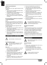
Mounting the dust bag
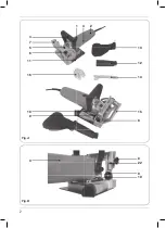
Fig. A
• For dust extraction the dust bag (13) can be
used. Connect the dust extraction adapter (12)
to the machine, then connect the dust bag (13)
to the adapter.
• Empty the dust bag regularly so that the
vacuuming performance remains intact.
• A vacuum cleaner can be directly connected
to the dust extraction adapter when use of a
vacuum cleaner is preferred.
5. OPERATION
Never use the spindle lock while the
machine is running.
Switching on and off
Fig. A
• To switch the machine on slide the on/off
switch (1) forwards.
• To switch the machine off, depress the on/off
switch (1), the switch will automatically move
to the ‘off’ position.
Never use the spindle lock to stop the
motor.
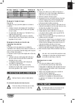
Marking the workpiece
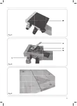
Fig. E
Before starting with the Biscuit Jointer the
workpieces must be marked as following.
• Place the two surfaces which must be
connected, with their connecting side to each
other
• Clamp the work pieces and mark the center of
the groove by drawing a perpendicular line
• Several joints will be required for larger
workpieces. The distance between two drawn
lines should be at least 10cm.
Sawing grooves
Fig. F
• Set and check the cutting depth on the
machine
• Set the angle on the machine
• Set the height on the machine, take care for
setting the height, the groove for the biscuit
dowel must be in the middle of the workpiece.
• Make sure the workpiece is securely clamped
• Position the machine on the workpiece, the
marked centerline (15) must be in line with the
line drawn on the workpiece
• Hold the machine with both hands and switch
the machine on.
• Push the motor base carefully forward as far
as possible.
• Move the motor base backward and switch the
machine off.
For workpieces thinner than 16 mm it is
not possible to cut the groove in the
middle of the workpiece without adding
an adjustment plate below your
workpiece (fig. G).
Joining the workpieces
When the grooves in both workpieces have been
made the workpieces can be joined together.
• Put glue in both grooves.
• Place the biscuit dowel in the groove of one
workpiece.
• Place the other workpiece on the biscuit
dowel.
• Fasten the workpieces and wait till the glue is dry.
User tip for connecting two workpieces
• Saw a groove as big as one biscuit into the first
workpiece
• Place the biscuit with good glue (according the
material) into the groove
• Saw a longer groove into the other workpiece
• Now both workpieces can be positioned easily
towards each other (clearance to correct)
• Fasten the workpieces and wait till the glue is dry
Move the machine in the same direction
as the direction of rotation. See arrow on
top of the machine.
Summary of Contents for BJM1009
Page 2: ...2 Fig A Fig B 8 22 9 10 13 12 14 15 8 1 3 2 3 6 11 4 5 7 16 10 9...
Page 3: ...3 Fig C Fig E Fig D 20 14 17 18 5...
Page 4: ...4 Fig F Fig G 21 15...
Page 107: ...107 RU EN 60745 2 O 16...
Page 109: ...109 RU C D 4 20 17 14 18 17 17 17 20 4 A 13 12 13 5 A E 10 F 15...
Page 110: ...110 RU 16 G B 3 10 10 10 6 H...
Page 111: ...111 UK 2012 19 U 900W BJM1009 O Ferm Ferm 2 4 1 2 3 4 5 6 1 1 1...
Page 113: ...113 UK 16 EN60745 1 5 2 3 3 9 9 16...
Page 115: ...115 UK 5 E 10 F 15 16 G B 3 10 10 10...
Page 116: ...116 UK 6 Ferm Ferm 2012 19 EU...
Page 118: ...118 AR 2 61 NE 54706 5 1 3 3 9 9 16 01 01 0 8 12 0 8 0 10 12 15 10 10 0 20 15 20 12 3 14 0...
Page 119: ...119 AR 6 6 12 6 8 22 8 4 02 5 71 41 71 81 71 71 02 31 21 31 5 1 1 01 51...
Page 120: ...120 AR 61 3 01 01 01 6 EC 2012 19...
Page 127: ...127 MK EN 60745 2 16...
Page 129: ...129 MK 18 17 17 17 20 4 A 13 12 13 5 A 1 1 off E 10 cm F 15 16 mm G...
Page 130: ...130 MK B 3 10 10 10 6...
Page 131: ...131 MK 2012 19 EU...
Page 133: ...133 Exploded view...
Page 134: ...134...
Page 136: ...WWW FERM COM 2020 FERM 2005 18...


