ENG
6
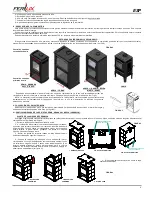
APPLIANCE DESCRIPTION
1. DOOR
Main access to the stove. Use it for adding the fuel.
2. DOOR HANDLE
Pull the handle to open the door. Push the handle to shut the door (See Section II ‘
Opening and closing the door
’).
3. PRIMARY AIR VENT
The fire is controlled by a primary air intake which controls the maximum and minimum flow of air to the fire. Use it to obtain a slow and economical fire or a quick and high
calorific fire (See Section IV ‘
Regulation of the fire
’).
4. SECONDARY AIR VENT
Air intake to the top of the combustion chamber. It prevents the glass from getting dirty.
5. CHAMBER
The air of the room circulates through this chamber. (In DENIA, GRANADA and NERJA (CERÁMICA) stoves, this chamber is externally covered with pieces of ceramic).
6. CHAMBER AIR OUTLET
DO NOT COVER, the air expelled can reach more than 250 ºC and could burn the object and even damage the appliance.
7. SMOKE OUTLET
It connects with the flue pipe which expels the combustion fumes outside. It must be built as explained in the installation section.
(In stoves DENIA, GRANADA, VALLE, BRITO, DÚRCAL, GUADIX and LAWA the smoke outlet can be laid either in horizontal or in vertical position. (See Section ‘Smokes
outlet’). The elbow joined shown in the diagram is not provided with the stove)
8. OVEN
Only in model DÚRCAL, NERJA and FORNO
REFERENCES FOR INSTALLATION
Your supplier is specialized in the installation of all the products CHIMENEAS Y BARBACOAS FERLUX, S.A.U. We recommend you, for your safety and complete satisfaction
with the appliance working, to ask your supplier for advice to installing the product acquired.
The appliance must be installed complying with the local regulations.
However, if you decide to make the installation on your own, following we give you some basic advice:
The appliance must be installed in a floor resistant enough to support the appliance weight without problem.
It is important to place the air vent grill in such a way that it cannot become obstructed.
All materials on or within the walls (floors, walls, ceilings) around the chimney that are combustible or could be damaged by heat must be removed if the chimney
is in contact with these walls.
The insulation required to achieve this should be of an adequate thickness of incombustible insulating materials such as:
- Special high temperature rock wool with aluminium on one side.
- Ceramic fibres with aluminium on one side, with or without an air cavity.
The insulation work must be carried out with the greatest care.
An access point must be made before installation to allow future cleaning of the flue connector and the chimney pipe.
VENTILATION DUCT
The chimney flue must be built by the rulebook. Some of the most important are:
Minimum height 4 meters.
We advise you to use a pipe with thermal insulation.
If possible, avoid diagonal parts. Never install elbows with more than 45 º, and use radius with a big curvature.
The ending of the chimney is very important, the height from the roof as well as the type of ending. Ask your supplier for advice.
Connect only one appliance for pipe.
In case of a double outlet pipe, we advise you to cancel one of them.
The ideal chimney draught is between 10 and 15 Pa (1 to 1.5 mm of water column).
The chimney connection with the stove must have a minimum overlap of 25 mm according to Standard UNE-EN 13240.
If necessary, the chimney and flue liner should be cleaned beforehand.
WARNING! Connecting more than one appliance to the same flue is forbidden.
Check the condition of the existing flue carefully, as many are too old or inappropriate, an unusual build-up of dirt could present a hazard or, the most frequent
case, they may not be suitable or designed to withstand the smoke temperatures of 500ºC that have been measured in fireplaces with a lively fire.
An over-sized flue can be too large to heat up and can therefore cause fireplace performance problems. To avoid these, we recommend re-lining the entire flue in these
cases.
FIGURE 1
DENIA - GRANADA
VALLE – BRITO – DURCAL – GUADIX
BELEN – MARTA – ROSSY
NERJA – FORNO
LAWA


