WerkstatthandbuchWorkshopmanualManuel de réparationManuel d´atelierManuale per I´officina
MotorEngineMoteurMotore
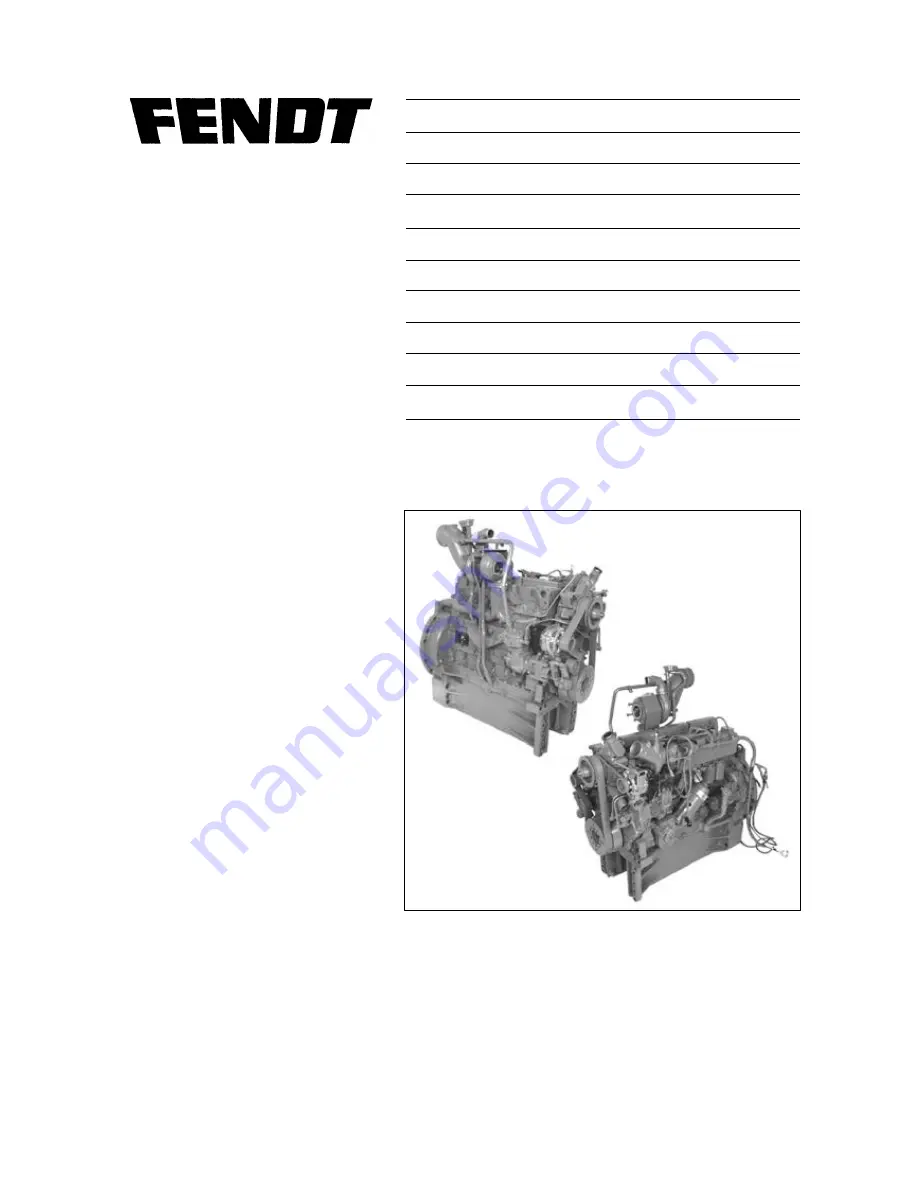
MAN D 0836 LE
(Mechanical part)
X990.005.039.010
Page 1: ...Werkstatthandbuch Workshopmanual Manuel de r paration Manuel d atelier Manuale per I officina Motor Engine Moteur Motore MAN D 0836 LE Mechanical part X990 005 039 010...
Page 2: ...le or parts without our prior authorisation is prohibited Pebli par le Service Apr s vente de ACGO GmbH Co Marktoberdorf Tous droits r serv s Printed in Germany Cette brochure ne peut tre reproduite n...
Page 3: ...anical part Ausgabe 05 2001 Xaver FENDT GmbH CO Ein Unternehmen der AGCO Corp Maschinen und Schlepperfabrik Marktoberdorf Bayern Germany Postfachadresse D 87609 Marktoberdorf Postfach 1155 Telefon 0 8...
Page 4: ...he nderungen die zur Verbesserung des Produktes notwendig werden vorbehalten Nachdruck und Vervielf ltigung jeglicher Art auch auszugsweise bedarf unserer schriftlichen Genehmigung FOREWORD This works...
Page 5: ...El presente Manual de Rparaciones ha sido elaborado para los talleres de nuestros servicios oficiales y comprende todos los trabjos de montaje y desmontaje qu son necesarios para la sustituci n de pi...
Page 6: ...zione di un officina Attrezzi speciali sono limitati al minimo indispensabile e vengono elencati alla fine di questo manuale Per quanto riguarda la manutenzione si prega di consultare le istruzioni pe...
Page 7: ...refitting the thermostatic valve 57 Removing and refitting water pump 58 Removing and refitting coolant pipe 62 Layout of fuel system 63 Fuel pre filter Cartridge 64 Purging Air from Fuel Supply Syste...
Page 8: ...fitting oil cooler 106 Removing and refitting oil pan 108 Removing and refitting oil pump 111 Removing and refitting splash nozzle 114 Checking Start of Delivery VP44 115 Fuel Injection Pump VP 44 Mou...
Page 9: ...PS at 2150 rpm 217 HP D 0836 LE 504 146 kW 200 PS at 2150 rpm 196 HP Max torque to ISO 1585 88 195 EWG D 0836 LE 501 1175 Nm at 1400 rpm D 0836 LE 502 1070 Nm at 1400 rpm D 0836 LE 503 970 Nm at 1400...
Page 10: ...size 4 00 4 03 mm 157 159 Oversize 4 20 4 23 mm 165 167 3 Standard size 111 50 111 52 mm 4 389 4 390 Oversize 0 5 mm 112 00 112 02 mm 4 409 4 410 4 Max permissible taper over length of cylinder PMTAB...
Page 11: ...imensions Standard 76 981 77 000 mm 3 031 3 032 Under size 0 10 mm 004 76 881 76 900 mm 3 027 3 028 2 Con rod bearing journal diameter Standard 69 981 70 000 mm 2 755 2 756 Under size 0 10 mm 004 69 8...
Page 12: ...Housing bore for main bearing 82 000 82 022 mm 3 228 3 229 Axial play 0 040 0 105 mm 002 004 Spread of main spearing shells 0 5 1 5 mm 020 059 PMTAB_Picture max permissible crankshaft axials play 0 20...
Page 13: ...le Con rod bearing PM Picturemodule Text module PMTAB_Picture 1 42 050 42 066 mm 1 655 1 656 2 32 78 32 88 mm 1 290 1 294 Con rod journal width 33 0 33 1mm 1 299 1 303 PMTAB_Picture Fit con rod bearin...
Page 14: ...50 63 60 mm 2 500 2 503 Piston projection above crankcase 0 0093 0 391 mm 004 015 2 42 003 42 009 mm 1 6537 1 6539 Piston pin diameter 41 994 42 000 mm 1 6533 1 6535 3 107 891 107 900 mm 4 2477 4 248...
Page 15: ...size 16 250 16 268 mm 640 641 2 Valve guide outer diameter Standard size 16 028 16 046 mm 631 632 Oversize 16 278 16 296 mm 641 642 3 Standard size Intake valve 10 8 10 9 mm 425 429 Exhaust valve 11 0...
Page 16: ...Picturemodule Text module PMTAB_Picture 1 Intake valve 9 965 9 980 mm 3923 3929 Exhaust valve 9 950 9 965 mm 3917 3923 Wear limit max 0 1 mm 0039 2 Valve recess Intake valve 0 25 0 71 mm 010 028 Exha...
Page 17: ...7 19 970 mm 7857 7862 Wear limit 0 08 mm 003 PMTAB_Picture Valve tappets 1 Tappet housing bore Standard size 20 000 20 021 mm 787 788 Oversize 20 250 20 271 mm 797 798 Tappet outer diameter Standard s...
Page 18: ...int 230 Figures in degrees relate to the crankshaft angle PMTAB_Picture Layout of engine timing 1 Crankshaft gear 2 Intermediate timing gear 3 Camshaft gear 4 Injection pump drive gear 5 Oil pump driv...
Page 19: ...3 2 PSI Oil splash nozzle orifice 1 75 1 85 mm 069 073 PMTAB_Picture Oil pump drive gear 1 16 mm 630 2 D 0836 LE 501 502 31 925 31 950 mm 1 257 1 258 D 0836 LE 503 504 31 920 31 950 mm 1 257 1 258 Hou...
Page 20: ...eller and housing 0 5 0 9 mm 020 035 2 Impeller diameter 136 mm 5 354 3 Bearing location in housing 54 940 54 970 mm 2 163 2 164 Bearing diameter 54 981 54 994 mm 2 1646 2 1651 4 Bore in hub 25 000 25...
Page 21: ...000 000006 A b 12 14 Capitel Docu No Index Date Version Page Service Data Turbocharger PM Picturemodule PM Picturemodule Text module Manufacturer KKK D 0836 LE 501 502 503 504 HX40 8274AW H18WA8 PMTAB...
Page 22: ...ch Type DSLA 154 P 625 N of orifices 6 Nozzle opening pressure Nozzle holder new 320 8 bar 4641 116 PSI Nozzle holder used 300 8 bar 4351 116 PSI Nozzle injection pump with vane cell feed pump and aut...
Page 23: ...pe EV operationg method pre engaged drive Starter pinion gear Number of teeth 11 Module 3 Nominal voltage 24 Volt Nominal output 4 kW 5 36 HP PMTAB_Picture Generator Manufactured Bosch Type KC Operati...
Page 24: ...tial torque 150 Nm 110 63 lbf ft Angular torque 90 100 Angular torque 90 100 Flywheel on crankshaft Initial torque 100 Nm 73 76 lbf ft Angular torque 90 100 Con rod bearing caps Initial torque 50 60 N...
Page 25: ...ft Angular torque 90 100 Banjo bolt of solenoid valve 10 15 Nm 7 38 11 06 lbf ft Knuckle pin clap of turbocharger 12 Nm 8 85 lbf ft Nozzle holder in cylinder head 70 Nm 51 63 lbf ft Nozzle adjusting...
Page 26: ...5 0 55 32 M10 1 50 0 36 88 70 0 51 63 85 0 62 62 M12 75 0 55 32 105 0 77 44 125 0 92 20 M12 1 5 75 0 55 32 110 0 81 13 130 0 95 88 M12 1 25 80 0 59 00 115 0 84 20 135 0 99 57 M14 115 0 84 20 170 0 125...
Page 27: ...turemodule Text module Tightening cylinder head bolts following repair work Only for Torx heads No tightening for Torx head screws PMTAB_Picture Note Only use new cylinder head bolts do not re use bef...
Page 28: ...earing wear quickly resulting in mechanical damage Text module Lack of power For satisfactory power observe correct settings for Bullet start of fuel delivery valves clearance engine control at full l...
Page 29: ...edule Operation on not allowed high slanting angles High pressure within crankcase e g Oil release valve failure Crank case venting or worn piston rings Text module Turbocharger compressor coking Can...
Page 30: ...ion Page View of engine D 0836 LE 501 PM Picturemodule Text module PMTAB_Picture 1 Fuel injection pump VP44 7 Fuel filters 2 Lubricant cooler 8 Turbocharger 3 Lubricant filter 9 Lubrication oil turboc...
Page 31: ...rew compression recorder onto test adaptor and insert test sheet Using the starter motor turn engine until the indicator no longer deflects Connect compression recorder with test adapter to the other...
Page 32: ...Fit engine actuation device to flywheel housing Remove crankcase venting pipe Accurately set valve play of 1st cylinder Actuate engine against rotating direction to approx 40 C before TDP Set dial gau...
Page 33: ...der PM Picturemodule PMTAB_Picture Engine must be cold for adjusting valve clearance max coolant temperature 50 C 122 F Setting valve clearance PMTAB_Picture Rotate crankshaft using turning device unt...
Page 34: ...Docu No Index Date Version Page Setting valve clearance PM Picturemodule PMTAB_Picture Insert gauge between valve shaft and rocker With valve setting tool loosen lock nut and turn setting screw until...
Page 35: ...ensors Remove fuel lines to flame booster plug and to solenoid valve Remove wiring harness Remove fuel filter Remove fuel pre filter with manual lifting pump Remove collars of the injection lines and...
Page 36: ...remodule PM Picturemodule PM Picturemodule PMTAB_Picture Removing turbocharger Remove crankcase venting pressure control valve Remove air intake pipe from compressor to intake manifold Remove air inta...
Page 37: ...reign objects Examine oil feed and return lines for eventual damage jamming and leaks Replace all gaskets Refitting the turbocharger occurs in the inversed sequence as the removing For refitting use n...
Page 38: ...ture Removing the exhaust manifold Remove turbocharger Note Protect exhaust port on turbocharger from contamination Unscrew and remove nuts from exhaust manifold PMTAB_Picture Guidance pins visible on...
Page 39: ...MTAB_Picture Loosen clamping bolts and remove rocker arm Dismantling overhauling and reassembling rocker assembly Removing the cylinder head Drain coolant remove lines from injection nozzles Remove in...
Page 40: ...In the event of repeated leaking use the straight edge to chek the sealing faces of cranskcase and cylinder head for distortion Uneven cylinder heads can be surface ground by up to 1 mm Remachined se...
Page 41: ...tween cylinder heads and manifolds we recommend the following steps Refit cylinder heads using guidance bolts Oil the new cylinder head bolts and their rest surface with Optimoly Withe T paste Hand ti...
Page 42: ...e PM Picturemodule PM Picturemodule PMTAB_Picture Tighten bolts slightly and align rocker arms with valves Subsequently tighten bolts to specified torque PMTAB_Picture Set valve clearance chap 2010 Re...
Page 43: ...M Picturemodule PM Picturemodule PMTAB_Picture Dismantling the rocker arm assembly Remove rocker arm assembly Clamp rocker bearing bracket in a vise use non metallic jaws PMTAB_Picture Remove circlip...
Page 44: ...imol White T paste Refit circlip on the rocker shaft Coat rockershaft and bearing bracket bore with Optimol White T paste Slide stop washer outer spring stop washer rocker arm end flush with bushing f...
Page 45: ...e fitting lever down and remove valve collets Lift lever and swing to one side Caution Beware of spring tension Danger of injury Remove upper spring plate 2 valve spring 3 and washer 4 Turn cylinder h...
Page 46: ...Note Make sure collets fit properly they can cause severe damage by springing out PMTAB_Picture Measuring valve recess Position gauge holder with dial gauge at the cylinder head Press tip of gauge ont...
Page 47: ...3001 and up 19 02 2001 2010 000008 G a 3 3 Capitel Docu No Index Date Version Page Removing and refitting valves PM Picturemodule PMTAB_Picture 1 Copper Sealing ring 2 Injection nozzle projection 2 68...
Page 48: ...ead on a press with the combustion chamber side facing upwards Use a mandrel to press out the valve guide PMTAB_Picture Refitting the valve guide Lubricate new valve guides and using a mandrel and spa...
Page 49: ...e PM Picturemodule PM Picturemodule PM Picturemodule PMTAB_Picture Using a valve lathe machine a 3 4 mm 118 157 wide groove in the valve valve seat inserts Insert internal extractor claw in the machin...
Page 50: ...ylinder head above 200 C 392 F causes the core plugs to become loose and they must be replaced To do this clean core holes blow out ducts and press in new core plugs using a mandrel and LOCTITE 270 PM...
Page 51: ...ip 4 Lubricating nipple 5 Mains supply 6 Solenoid valve with coil 7 Guide tube 8 Swivel arm 9 Guide mandrel 10 Cutter 11 Allen screw 12 Chuck 13 Lubricating nipple 14 Clamping lever 15 Guide ball 16 T...
Page 52: ...ve seat by evenly turning the crank handle in clockwise direction this moving the thurst nut at the same time Note Turn the crank firmly and evenly but never in anticlockwise direction since this coul...
Page 53: ...ence value will be value of valve recess If the cylinder head faces are re machined max 1 mm 039 it is necessary also to re machine the inserts in order to obtain the correct valve recess When fitting...
Page 54: ...ning movements Note Do not allow grinding paste to come into contact with the valve stem and guide PMTAB_Picture The re grinding process of the valve seat must produce a perfect closed grinding patter...
Page 55: ...olant Drain coolant only on a cooled down engine as described Note Collect coolant in a pan and dispose of it properly PM Picturemodule PM Picturemodule Caution Hot coolant may cause severe burns duri...
Page 56: ...water and antifreeze based on Ethylene Glykol and corrosion preventer Refer to Lubricants Chapter l 0000 Reg A Use a proper ratio water Antifreeze Tighten screw on oil filter body using a new gasket F...
Page 57: ...alve Check correct operation of thermostat as following Place thermostatic valve in pot filled with water Heat water Measure opening temperature with an adequate thermometer Measure opening distance R...
Page 58: ...lines Remove V belt Remove cooling lines to air compressor Remove generator belt tensioner screw 1 top left Remove generator pod 2 on the top left Remove hub of Viscosity clutch PMTAB_Picture Unsrew...
Page 59: ...Overhauling the water pump 1 Impeller 2 Sliding ring gasket 3 Water pump bearing 4 Pump housing 5 Circlip 6 V belt pulley Remove water pump PMTAB_Picture Clamp water pump lift section in a vise use n...
Page 60: ...odule PM Picturemodule Text module PMTAB_Picture Using a pressinf bush press bearing into pump housing until contact is made Insert circlip Press pulley into shaft flush with the plate PMTAB_Picture I...
Page 61: ...eds to be replaced only if water is dripping while the engine is running or after it is switched off Text module Fitting instructions for sliding ring gasket The ring gasket must be mounted wet Coat t...
Page 62: ...hile engine is cold Use a clean pan with sufficient capacity Remove injection lines Remove intake pipe Disconnect temperature sensor PMTAB_Picture Unscrew and remove coolant pipe Remove gasket and cle...
Page 63: ...Capitel Docu No Index Date Version Page Layout of fuel system PM Picturemodule Text module ETNum list PMTAB_Picture 1 Pre filter with manual fuel lift pump 2 Fuel lift pump 3 Fuel filter 4 Measuring p...
Page 64: ...Picturemodule PMTAB_Picture Cleaning pre filter Disassemble pre filter Unscrew filter body PMTAB_Picture Clean Filter body 1 and Sieve 2 with clean diesel fuel and dry it with compressed air Re assemb...
Page 65: ...filter Disconnect fuel lines 1 Remove scews 2 and take off fuel filter Reassemble in reversed order and connect fuel lines with new sealing rings Purge air from fuel supply system PMTAB_Picture Replac...
Page 66: ...he fuel filter by one to two turns PMTAB_Picture Actuate manual fuel lifting pump until fuel flows without any bubbles Repeat this procedure on the second purging screw Check for leaks within the fuel...
Page 67: ...on the heater plug as far as possible Wetten threads with Curil T sealant Screw in heater plug to the end position of the lock nut and align with fuel line Reconnect fuel line and electrical connecti...
Page 68: ...nstant tension on the power belt PMTAB_Picture Tensioner must be adjusted as follows 1 New tensioner distance A 92 1 mm 3 62 04 2 If distance A 100 mm 3 94 turn excenter to right to reach a distance o...
Page 69: ...m tensioner and remove powerbelt from the pulley Refitting Place powerbelt onto pulleys of crankshaft generator and coolant pump Set tensioner completely back Place powerbelt onto pulley release tensi...
Page 70: ...Position tension gauge 2 in the center between the generator pulleys and the crankshaft Slowly push pressure pad 3 down until the spring snaps out audibly and the indicator arm moves upwards Continued...
Page 71: ...engages in these positions during start up On 6 cylinder engines these points are staggered by 180 i e threre are 3 points To replace the starter ring gear see chapter 2000 Reg G PM Picturemodule PMT...
Page 72: ...from the battery Remove connections B D and W from the generator PMTAB_Picture Remove V belts Unscrew bolts arrows Remove generator PMTAB_Picture Refitting generator Refit the generator Check and if n...
Page 73: ...nd unscrew tensioning nut 2 Push generator toward the engine and take off the power belt Unscrew the upper screws 3 Unscrew the lower screws 4 Remove generator Check screw and guide for damage i e cra...
Page 74: ...fan frame support bracket Remove oil feed line air intake line and compressed air line Note For ease of assembly mark position of excentric bearing support on timing case PMTAB_Picture To remove air c...
Page 75: ...g plate 3 to 30 Nm 22 13 lbf ft Loosen nut 2 Press out drive gear fit mounting plate 3 with 4 screws 4 at the bottom side of the drive gear 2 PMTAB_Picture Screw 5 to be screwed into central threaded...
Page 76: ...g plate 1 out of drive gear Remove mounting plate Screw and tighten connection fittings for coolant and compressed air using new gaskets into the cylinder PMTAB_Picture Refitting the compressor Thorou...
Page 77: ...turned consequently PMTAB_Picture Place 4 screws and tighten them in such a manner that the control eccentric can still be moved Screw in the screws of the rear side Place eccentric into the marked po...
Page 78: ...on clearance can be read on the dial gauge If the pinion clearance is not OK then it needs to be adjusted PMTAB_Picture Checking backlash Check backlash between drive wheel and camshaft timing gear by...
Page 79: ...heck vibration damper and washer for damage replace if necessary Remove oil splash ring PMTAB_Picture Replacing crankshaft front seal Lever out rotary shaftt with special tool PMTAB_Picture Apply mult...
Page 80: ...o screws on opposite side replace with two guide mandrels special tool Unscrew all screws and remove clutch flange Using two M10 ease off the flywheel Remove clutch flange and disc Danger The flywheel...
Page 81: ...el PMTAB_Picture Note Since the maximal permissible axial run out of the starter ring gear must not be exceeded it is advisable to determine flywheel deviation at ring gear contact face before ring ge...
Page 82: ...g and refitting crankshshaft seal flywheel PM Picturemodule PM Picturemodule PMTAB_Picture Rermoving shaft seal Remove flywheel Lever out sealing ring with special tool PMTAB_Picture Refitting the sha...
Page 83: ...u No Index Date Version Page Removing and refitting flywheel housing PM Picturemodule PM Picturemodule PM Picturemodule PMTAB_Picture Removing flywheel housing Unscrew and remove the two screws M16 PM...
Page 84: ...wo fairly long guide pins Remove flywheel housing Caution The flywheel is very heavy Use suitable hoisting gear Remove gasket residues from flywheel housing and crankcase PMTAB_Picture Note If the rep...
Page 85: ...ase cover Remove cover PMTAB_Picture 1 Crankshaft timing gear observe 2 2 2 on intermediate gear 2 Intermediate gear 3 Injection pump drive gear 4 Oil pump drive gear 5 Crankshaft timing gear observe...
Page 86: ...placing crankshaft axial stop If necessary replace cranshaft axial stop thrust washer PMTAB_Picture Removing timing case Unscrew and remove screws SW13 between oil pan and timing case PMTAB_Picture Un...
Page 87: ...specified torque PMTAB_Picture Refitting intermediate gear Position intermediate gear Align camshaft and crankshaft with appropriate markings insert intermediate gear Note Position of crankshaft timin...
Page 88: ...ndex Date Version Page Removing and refitting the timing case PM Picturemodule PMTAB_Picture Refit timing case cover with new gasket Insert screws and tighten Refit vibration damper Centaflex coupling...
Page 89: ...otographs show the driving gears and timig case removed The camshaft can be replaced without removing these parts PMTAB_Picture Put engine upside down in order to have the pushrods sliding toward the...
Page 90: ...the crankcase Note Bearing bushes must be machined to the required size The crankcase must be cleaned with compressed air oil channels after this operation PMTAB_Picture Refitting the camshaft Slide g...
Page 91: ...enove dispstick guide tube and undo oil fliter cap Place a jack unscrew and remove screws 1 PMTAB_Picture Insert 2 M8x60 screws arrowed and carefully separate oil pan and intermediate flange Clean fla...
Page 92: ...n repairing con rod bearing journals use bearing shells of the relevant repair size Check spread of new bearing shells Place bearing shells together on a level surface Measure and note dimension A Mea...
Page 93: ...from the center outwards and remove Take off bearing caps and arrange in order of assembly Note Bearing cap positions in relation to the crankcase are identified by numbers bearing number 1 is at the...
Page 94: ...aring shells together on a level surface Measure and note dimension A repeat for B Spread A B PMTAB_Picture Refitting the cranshaft Clean oil ducts in crankcase and camshaft with dry compressed air PM...
Page 95: ...fied torque Note Faulty bearing caps cannot be replaced uniquely PMTAB_Picture Checking end play Note The end play of the crankshaft is determined by the condition of the main bearing Position gauge h...
Page 96: ...s applying light knocks with a plastic hammer if necessary Note Con rod bearing caps are numbered to match the big end and crankcase Arrange in appropriate order PMTAB_Picture Using a piece of hard wo...
Page 97: ...ion see Service data Make a note subtract piston diameter from largest measured cylinder diameter The resulting value is the piston clearance If clearance ist excessive cylinder liner and piston must...
Page 98: ...AB_Picture Fit con rod bearing shells into bearing caps Fit bearing caps making sure the numbers are matching Note Numbers on bearing cap and big end must be on the same side Chamfered side Arrow on c...
Page 99: ...e piston and depose it safely Note If the con rod needs replacing use ready to fit new bush or reconditioned con rod PMTAB_Picture Measuring big end con rod bore Screw on con rod bearing caps without...
Page 100: ...d refitting con rod PM Picturemodule PM Picturemodule PMTAB_Picture Measuring the piston projection Remove the cylinder heads Turn relevant piston to TDC Position gauge holder with dial on crankcase s...
Page 101: ...ing D ring PMTAB_Picture Removing piston rings Remove piston and con rod assembly Clamp con rod in a vise using non metallic jaws Set piston ring pliers to piston diameter PMTAB_Picture Position plier...
Page 102: ...e Removing and refitting the piston rings PM Picturemodule PM Picturemodule PMTAB_Picture Refitting piston rings Using piston ring pliers insert piston rings in relevant groove with Top facing upwards...
Page 103: ...the liner outer diameter an upper deviation of 0 5 mm 020 is permissible PMTAB_Picture Removing the cylinder liner Removing cooling oil nozzles chapter 2312 Reg G Usually the cylinder liner can be rem...
Page 104: ...a 1 1 Capitel Docu No Index Date Version Page Layout of engine lubrication PM Picturemodule Text module ETNum list PMTAB_Picture 1 Lubrication Gear pump 2 Pressure relief valve 3 Oil cooler 4 Main str...
Page 105: ...ilter lid 2 turns wait about 5 minutes until all the remaining oil has drained from the oil filter housing in the oil pan Remove cover completely PMTAB_Picture Pullt out filter cartridge with the cent...
Page 106: ...Removing oil filter Note Used oils and filter cartridges are hazardous waste Dispose properly Remove oil filter Unsrew drain plug arrowed from oil filter head and drain fluid into a container of adequ...
Page 107: ...ng and refitting oil cooler PM Picturemodule PMTAB_Picture Refit oil cooler Fit oil cooler to the oil filter head with new gaskets Position oil filter head on engine block using new gasket Place screw...
Page 108: ...ils are hazardous waste Dispose properly Respect safety regulations Pull out dipstick and remover filling cover Remove drain plug Arrows and drain oil Use a recipient with sufficient capacity PMTAB_Pi...
Page 109: ...rom the oil pan Note For ease of reassembling note the screws sequence I e short long PMTAB_Picture Insert two M8 20 screws at the rear of the oil pan arrowed and slowly press down the oil pan Clean t...
Page 110: ...cture Refitting the oil pan Coat oil pan sealing surface with sealing compound Terostat 63 avoiding bore holes Note The lenght of time between applying terostat 6 and assembling must not exceed 20 min...
Page 111: ...rator and the timing case cover Unscrew nut of pump gear wheel holding the crankshaft with a rotating device Remove washer and withdraw gear wheel from the cone using a puller Remove timing case PMTAB...
Page 112: ...vailable as special tools PMTAB_Picture Note The press in depth 16 mm of the driving shaft is determined by the spacer sleeve Make sure there are no signs of scoring on the shaft after pressing in PMT...
Page 113: ...ungreased drive shaft cone Fit washer screw on nut and tighten to specified torque Remove the fan frame Power belt vibration damper air compressor alternator and the timing case cover PMTAB_Picture Re...
Page 114: ...In the illustration on hthis page the crankshaft has been removed to allow a clear picture Unscrew and remove oil pressure valve 1 and nozzle 2 Remove nozzle and valve assembly PMTAB_Picture Check oi...
Page 115: ...l Docu No Index Date Version Page Checking Start of Delivery VP 44 PM Picturemodule PM Picturemodule PM Picturemodule PM Picturemodule PMTAB_Picture Remove cover Arrows PMTAB_Picture Set actuation too...
Page 116: ...hrough the TDP measuring hole If the flat part cannot be recognized turn the crank shaft further 360 with the actuation tool in order to place the flat part of the control shaft in frontt of the measu...
Page 117: ...tion Pump 0 79 Consequently Adjust TDP to reach 0 79 mm on dial gauge Note Scanning head of dial gauge runs into slanted surface of the control shaft Do not turn crankshaft any further risk of shearin...
Page 118: ...re Turn crankshaft using the actuation tool and loosen the visible screws 2 3 and 4 PMTAB_Picture Set first cylinder fan side using the actuation tool onto TDP arrow PMTAB_Picture Important 1 Cylinder...
Page 119: ...he TDP measuring hole Note Use dial gauge with ball tip R 1 mm 0 039 PMTAB_Picture Set dial gauge into 0 display position PMTAB_Picture Turn crankshaft back toward TDP until displacement X XX which is...
Page 120: ...PM Picturemodule PMTAB_Picture Important Bock injection pump Note sequence Loosen locking screw Pos A Remove spacer washer Pos B Tighten locking screw Pos A PMTAB_Picture Loosen TDP screw PMTAB_Pictu...
Page 121: ...dule PM Picturemodule PM Picturemodule PM Picturemodule PMTAB_Picture Loosen locking screw Pos 2 Put spacing washer Pos 1 into place Tighten locking screw Pos 2 Check start of delivery as decribed PMT...
Page 122: ...Version Page Fuel Injection Pump VP 44 Mounting Dismounting PM Picturemodule PM Picturemodule PM Picturemodule PM Picturemodule PMTAB_Picture Remove cover arrows left engine side PMTAB_Picture Put act...
Page 123: ...e Important 1 Cylinder will be in TDP Position if the flat section of the control shaft appears in the TDP hole If the flat section does not appear on the control shaft rotate the engine for another 3...
Page 124: ...position Arrow using the actuation tool PMTAB_Picture Important 1 Cylinder will be in TDP Position if the flat section of the control shaft appears in the TDP hole If the flat section does not appear...
Page 125: ...re Move crank shaft again into TDP Position until the marked displacement X XX will be reached e G Displacement on injection pump 0 79 means 0 79 mm 0 0311 displacement on dial gauge Note Scanning rod...
Page 126: ...ge Fuel Injection Pump VP 44 Mounting Dismounting PM Picturemodule PM Picturemodule PM Picturemodule PM Picturemodule PMTAB_Picture Important Block injection pump follow sequence Loosen locking screw...
Page 127: ...te Version Page Fuel Injection Pump VP 44 Mounting Dismounting PM Picturemodule PM Picturemodule PM Picturemodule PM Picturemodule PMTAB_Picture Pull out connector lock into arrow direction and then r...
Page 128: ...ule PM Picturemodule PM Picturemodule PMTAB_Picture Settings of a new injection pump VP 44 Start of delivery from TDP of first cylinder Fan Side Screws of injection pump drive pinion 4 x M8 are loose...
Page 129: ...turemodule PM Picturemodule PM Picturemodule PM Picturemodule PMTAB_Picture Tighten 4 x nuts M8 from pump flange arrows at 25 Nm PMTAB_Picture Tighten first visible screw M8 at 25 Nm PMTAB_Picture Loo...
Page 130: ...x Date Version Page Fuel Injection Pump VP 44 Mounting Dismounting PM Picturemodule PM Picturemodule PM Picturemodule PM Picturemodule PMTAB_Picture Put rear pump bracket into place PMTAB_Picture Put...
Page 131: ...smounting G Repair Fav 900 Chassis number 23 3001 and up 01 2000 2710 000002 G b 10 10 Capitel Docu No Index Date Version Page Fuel Injection Pump VP 44 Mounting Dismounting PM Picturemodule PMTAB_Pic...
Page 132: ...crements are available from 1 0 to 1 99 mm 039 to 78 Text module 2 Check for leaks Operate the hand lever At 20 bar 290 PSI below the specified opening pressure the nozzle must be free from droplets f...
Page 133: ...washer pressure screw compression spring and adjusting washer Remove the pressure pipe from the vise PMTAB_Picture Overhauling injection nozzles using a small piece of wood and petroleum or diesel fue...
Page 134: ...the nozzle body by one third and released it must drop back into the position by its own weight Fit injection nozzle observing the location of pins PMTAB_Picture Screw on threated union and tighten t...
Page 135: ...Index Date Version Page Replacing Injection valve with needle Motion sensor PM Picturemodule PM Picturemodule PM Picturemodule PM Picturemodule PMTAB_Picture Disconnect connector X173 Needle motion s...
Page 136: ...needle Motion sensor PM Picturemodule PM Picturemodule PM Picturemodule PM Picturemodule PMTAB_Picture Lead Cable through special tool MAN 80996030246 Place special tool and unscrew the injector PMTAB...
Page 137: ...alve with needle Motion sensor PM Picturemodule PM Picturemodule PM Picturemodule PM Picturemodule PMTAB_Picture Put new usit gaskets on the hollow screw on both sides of the return line PMTAB_Picture...
Page 138: ...v 900 Engine Generalities Special tools A General Fav 900 chassis number 23 3001and up 19 03 2001 9920 000004 A a 1 7 Capitel Docu No Index Date Version Page Special tools PM Picturemodule PMTAB_Pictu...
Page 139: ...sor 80 99603 0240 7 Puller for injection valves 80 99602 0011 Adaptor 80 99602 0059 8 Fitting tool for injection valve 80 99606 0008 9 Socket wrench for injection valve 80 99603 0024 10 Extractor for...
Page 140: ...v 900 Engine Generalities Special tools A General Fav 900 chassis number 23 3001and up 19 03 2001 9920 000004 A a 3 7 Capitel Docu No Index Date Version Page Special tools PM Picturemodule PMTAB_Pictu...
Page 141: ...orque angle 80 99607 0134 22 Piston ring clamp 80 99613 0035 23 Sliding bush 108 mm 83 09144 0057 24 Dial gauge bracket 80 99605 0172 25 Piston ring pliers 83 09144 6090 26 Scanner gauge 0 2 0 25 0 35...
Page 142: ...v 900 Engine Generalities Special tools A General Fav 900 chassis number 23 3001and up 19 03 2001 9920 000004 A a 5 7 Capitel Docu No Index Date Version Page Special tools PM Picturemodule PMTAB_Pictu...
Page 143: ...for valve rod bushings 80 99604 0106 38 Press in and out device for valve guides including pressing plate for valve seat rings 80 99604 0050 Device consisting of Press mandrel for valve guides 80 9960...
Page 144: ...9920 000004 A a 7 7 Capitel Docu No Index Date Version Page Special tools Text module Tools to be manufactured Guide mandrel for flywheel assembly Material made from M14 140 PM Picturemodule Text mod...