background image

28

212TOF

(400060-834)

!

"

#

$

!

"

§

Bandsaw

FB 510/610/710 & FB 710 c-tech

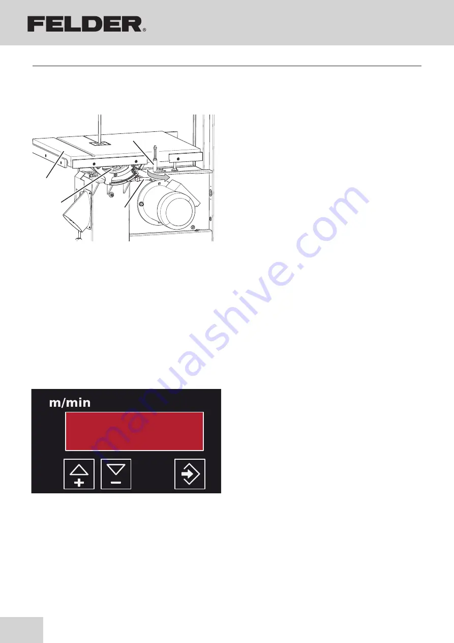
7.7.8 Tilting the table

Fig. 7-15: Positioning

The machine working table can be tilted up to an angle 

from -5° (FB 500: -10°) up to +45°.

Adjusting the angle:

To tilt, remove the table padding to enable the saw belt 

to move through the table unimpeded. Open the clam-

ping screw with the supplied spanner and tilt the table to 

the desired angle, which is displayed on the mitre scale. 

Tighten the clamping screw again. 

Positioning -5° or -10°:

• Swing away the stop

• Adjusting the angle

To tilt the table back to its normal position, loosen the 

clamping screw once again and tilt the table up to the 

stop in the 0° position and clamp it in that position.

(Swing back the stop)

!

Work bench

"

Clamping screws

#

Lever

$

Fence - 0°

Operation

7.8 Cutting speed (c-tech)

Variable cutting speed of 400 - 1400 m/min  

Increase or decrease the speed in steps using the  

arrow keys:

• 

Touch control input mode: ± 50 m/min

• 

press and hold: ±100 m/min

Press ENTER to confirm the value.

The speed can also be altered whilst the machine is in 

operation

!

Move the arrow UP

"

Move the arrow DOWN

#

Enter key

Fig. 7-16: Set the speed (c-tech)

Summary of Contents for FB 510

Page 1: ...Dok ID 424033 901_02 Englisch 2021 03 05 Keep this manual handy and in good condition for continual reference Translation User manual Bandsaw FB 510 610 710 FB 710 c tech...

Page 2: ...0 5223 58 50 0 Fax 43 0 5223 56 13 0 Email info felder at Internet www felder at FELDER A product of the FELDER GROUP Attention The machine must be inspected immediately upon arrival If the machine h...

Page 3: ...nts 9 2 6 Work safety 9 2 7 Personal protective equipment 10 2 8 Machine hazards 10 2 9 Other risks 10 3 Declaration of Conformity 11 4 Specifications 12 4 1 Dimensions and weight 12 4 2 Electrical co...

Page 4: ...thin work pieces 26 7 7 4 Cutting workpieces on the upright edge 26 7 7 5 Mitre cuts 27 7 7 6 Circular cuts 27 7 7 7 Diagonal cross cut of rectangular workpieces 27 7 7 8 Tilting the table 28 7 8 Cutt...

Page 5: ...is an integral part of the machine and must therefore be kept in the direct vicinity of the machine and be accessible at all times If the machine is sold rented lent or otherwise transferred to anothe...

Page 6: ...ld any questions arise please contact the manufacturer We reserve the right to make technical modifications to the product in order to further improve user friendliness and develop its functionality 1...

Page 7: ...structure is made of steel and can therefore be disman tled without problem Attention Used electrical materials electronic components lubricants and other auxiliary substances must be treated as hazar...

Page 8: ...roperly or em ployed for purposes other than those it was designed for The chapter entitled Safety offers an overview of all the important safety considerations necessary to optimise safety and ensure...

Page 9: ...must be briefed about all functions and potential dangers of the machine Spe cialist staff is a term that refers to those who due to their professional training know how experience and knowledge of r...

Page 10: ...espond to state of the art technology The machine is considered operationally safe when used properly Nevertheless there are some remaining risks that must be considered The machine runs at high elect...

Page 11: ...006 42 EG We hereby declare that the machine indicated below which corresponds to the design and construction of the model we placed on the market conforms with the health and safety requirements as s...

Page 12: ...FB 710 Total size mm 454 x 829 x 1995 460 x 985 x 2043 490 x 1110 x 2270 Package size mm 1200 x 800 x 2200 1200 x 800 x 2250 2365 x 720 x 1222 Net weight kg 250 320 400 Option Export 1110 x 490 x 236...

Page 13: ...particle emission and noise emission levels an inference cannot be made about whether additional safety measures need to be imple mented Factors which can significantly affect the emis sion level that...

Page 14: ...mmable and must not conduct electricity For this reason only use genuine FELDER dust extraction hoses Note As a rule all units must be vacuumed during use A time delayed socket is available as an acce...

Page 15: ...tension hand wheel BSMitre fence Accessories BTSaw blade tension indicator window BUOn Off switch CLLock wheel Wheel door CMVacuum connector CNTiltable table Fig 5 1 Overview Machine base frame Upper...

Page 16: ...rake which guarantees that all the moveable parts will come to a stop within 10 seconds once the machine has been switched off The brake shoes of the brake will wear out and thus need to be controlled...

Page 17: ...operate the machine in ambient temperatures from 10 to 40 C If the instructions are not followed damage may occur during storage Ensure that there is sufficient space to work around the machine Ensur...

Page 18: ...moved to set up the work table Thread the work table around the saw blade and mount to the machine using SKT screws lock washers and washers Re affix the table insert and positioning pin Fig 6 2 Work...

Page 19: ...bolster the machine The machine should be bolted to the floor with M10 screws for optimum stability however take care not to overtighten the fastening bolts as this will increase vi brations It is ad...

Page 20: ...et correctly by the manufacturer After connection check that the connection box and cable gland have been screwed tightly The dust extractor has to be connected to the machine in such a way as to be o...

Page 21: ...g to the instructions and test its function Only machine workpieces that can be safely placed on the machine and guided Carefully inspect workpieces for foreign matter nails screws which might impair...

Page 22: ...od whereas a coarse toothed saw blade is required for soft wood see Fig Tooth spacing 7 2 Blade selection and maintenance The gap between the individual teeth should be large enough to carry the mater...

Page 23: ...pacity change the wooden pad if the cutting gap is getting too large Operation 1 Disconnect the machine from the mains supply 2 Remove table insert and positioning pin Open wheel door 3 Loosen the bla...

Page 24: ...rusting backwards whilst cutting To adjust the position of the rollers simply loosen the clamping screw 7 5 Adjusting the saw blade guide The upper saw blade guide has to be lowered as closely as poss...

Page 25: ...xtensions or roll supports Fig 7 8 Rip cut 7 7 1 Longitudinal cut along the marked line Warning Risk of injury due to insufficient preparation It is only permitted to switch on the machine if for the...

Page 26: ...kpiece Use a push stick as depicted in Fig to prevent your hands from coming too close to the saw blade Fig 7 10 Push Stick 7 7 2 Cutting round workpieces in the transverse direction Use an auxiliary...

Page 27: ...ed in the figure Fig 7 12 Mitre cuts Fig 7 13 Circular cuts Use auxiliary equipment as depicted in the figure Fig 7 14 Cross cut 7 7 6 Circular cuts 7 7 7 Diagonal cross cut of rectangular workpieces...

Page 28: ...Positioning 5 or 10 Swing away the stop Adjusting the angle To tilt the table back to its normal position loosen the clamping screw once again and tilt the table up to the stop in the 0 position and c...

Page 29: ...tings may only be carried out by qualified personnel and in strict observance of the safety instructions Fig 8 1 Drive belts 8 2 Tightening replacing the drive belt Over time the drive belt will lose...

Page 30: ...damaged dur ing the process 8 5 Direction of cut and parallelism Fig 8 3 Remove the old wheel surface Fig 8 4 Direction of cut and parallelism If the cut using the longitudinal stop is still not para...

Page 31: ...etely If the machine is not in use the lubricant supply must be interrupted with the stopcock Fill the lubricant reservoir as required Lubricants Viscosity 20 mm2 s New at Format 4 40 C see catalogue...

Page 32: ...l with a constant spring Remove the wiper plate Insert new wiper plate Observe alignment The wi per plate must be threaded over the constant spring Put the wiper plate back against the flywheel Worn w...

Page 33: ...a fault develops 9 3 What to do after rectifying the fault Before switching the machine back on The fault and its cause are professionally repaired All safety equipment has been assembled according t...

Page 34: ...to the diameter of the wheel Defect or soiled wheel running surfaces Incorrectly aligned wheels Felder The saw blade is rupturing on the rear side Feed rate or pressure is too high during cutting Poor...

Page 35: ...econds 2 The actual speed is larger than 10 of the rated speed 1 Error in electrical system FELDER SEC 4 1 The converter is not stopping in the specified time 15 seconds 2 The frequency converter is t...

Page 36: ...Tirol Tel 43 0 52 23 58 50 0 Fax 43 0 52 23 56 13 0 E mail info felder at Internet www felder at FELDER KG KR FELDER STR 1 A 6060 Hall in Tirol Tel 43 0 5223 58 50 0 Fax 43 0 5223 56 13 0 Email info f...

Reviews: