background image

MVK 01/06 

All rights reserved by FEIN, in particular as these apply to trademarks. 
FEIN retains all powers of disposition such as copying and right of transfer


FRT:      EVO       WSB and WSG - Variants  

 15/118 

3.2.1.  Functional test / troubleshooting 

 Motor does not turn off, speed OK


 Motor stutters, but does not start


 Speed does not change  

  (only WSG ...70E) 


 Motor does not turn on (no 

function)   


 Close lever (only WSB)


 Check main power cable


 Check carbon brushes


 Check connection line 


 Check motor   


a)   Check for elec. continuity (ohms)


b)   Operate motor using isolating 
transformer


 Check elec. speed controller (at 

motor and connect external 
switching module  ) 

Replace parts if necessary 
or connect properly 

Replace parts if necessary 
or connect properly 

Replace elec. speed 
controller 

Replace switching module 

Check magnetic ring and 
replace if nec., check elec. 
speed controller properly 
snapped in 

 Motor starts immediately


 When button presed, motor starts briefly, but turns off immediately


Motor does not brake (only WSB) 


 Speed is not correct


 Motor turns on properly but only runs briefly before turning off 

again.   


OK 

OK 

OK 

Error 

Error 

Error 

2. 

1. 

Summary of Contents for EVO WSB Series

Page 1: ... 01 06 All rights reserved by FEIN in particular as these apply to trademarks FEIN retains all powers of disposition such as copying and right of transfer FRT EVO WSB and WSG Variants 1 118 1 Starting page ...

Page 2: ...FEIN retains all powers of disposition such as copying and right of transfer FRT EVO WSB and WSG Variants 2 118 Contents 1 Technical data 2 Maintenance 3 Electrical function test 4 Disassembly 5 Assembly 6 Tools for maintenance work 7 Modifications extras information for maintenance ...

Page 3: ...ut lock 7 221 35 7 221 34 Idle speed rpm 10 000 10 000 10 000 10 000 7 000 7 000 7 000 2 500 7 000 2 500 7 000 Power consumption W 800 1 200 800 1 200 800 1 200 1 200 800 1 200 Power output W 550 750 550 750 550 750 750 550 750 Mains connection type 1 1 Weight without cable kg 1 7 2 1 1 7 2 0 1 8 2 1 2 1 1 8 2 1 Safety class II II Grinding cutting wheel DIN ISO 603 Max diameter mm 115 125 115 125 ...

Page 4: ...ar as these apply to trademarks FEIN retains all powers of disposition such as copying and right of transfer FRT EVO WSB and WSG Variants 4 118 2 Maintenance 2 1 Regulations 2 2 Cleaning and care 2 3 Carbon brush replacement 2 4 Maintenance intervals ...

Page 5: ...pair may cause serious operational hazards for the user BGV A3 Carry out all routine tests in accordance with DIN VDE 0702 After repairs observe the regulations according to DIN VDE 0701 Part 1 Only use original FEIN replacement parts At initial operation observe the relevant accident prevention regulations of the trade and professional associations For information on intended use in Germany refer...

Page 6: ...RT EVO WSB and WSG Variants 6 118 Injury hazards through unintentionally switching on the unit Pull plugs before cleaning work Once a week more often when used frequently Check cables 290 for signs of damage Clean the cooling vents From outside blow out the interior of the electrical tool through the vent outlets using dry compressed air 2 2 Cleaning and care ...

Page 7: ...ushes with automatic switch off When checking the carbon brushes make sure that they are put back in the same position and can be moved easily in the carbon brush holder If the carbon brushes are run down to a length of 7 mm they must be replaced by new carbon brushes Only use original FEIN carbon brushes otherwise the regulations for EMC are not being observed Break in the carbon brushes for 20 m...

Page 8: ...sfer FRT EVO WSB and WSG Variants 8 118 2 4 Maintenance work After approx 300 operating hours Disassemble machine Thoroughly clean machine Replace bearing armature Replace magnetic ring Clean the speed controller do not moisten Check the cables and strands for abrasions Check for good fit of plugs and sockets Wash out gears using detergent and regrease ...

Page 9: ...ins all powers of disposition such as copying and right of transfer FRT EVO WSB and WSG Variants 9 118 3 Electrical function test 3 1 Minor functional test 3 2 Major functional test 3 3 Test data 3 4 Testing devices and aids 3 5 Wiring diagram Connection plan 3 6 Safety test final inspection ...

Page 10: ...wers of disposition such as copying and right of transfer FRT EVO WSB and WSG Variants 10 118 3 1 Minor functional test 3 1 1 Minor functional test WSB 8 115 WSB 13 125 3 1 2 Minor functional test WSG 8 115 WSG 13 125 WSG 9 125 WSG 13 125 S WSG 13 150 3 1 3 Minor functional test WSG 9 70 E WSG 13 70 E ...

Page 11: ...able 290 and protective tubing 270 for signs of damage Can the lever 480 be adjusted and does it snap in smoothly Can clamping bolt 680 be tightened loosened Is flange 670 free of damage Are the cooling and ventilation slots free of obstructions Is the fan wheel at the armature 750 free of damage With main power Plug in mains plug Start motor using switchpad 95 and lock it The motor must not start...

Page 12: ...13 125 S WSG 13 150 Without main power Check assembled cable 290 and protective tubing 270 for signs of damage Is the grinding wheel flange 900 free of damage Can the grinding wheel flange 910 be screwed on and off Are the cooling and ventilation slots free of obstructions Is the fan wheel at the armature 750 free of damage With main power Plug in mains plug Start motor using switchpad 95 and lock...

Page 13: ...Check assembled cable 290 and protective tubing 270 for signs of damage Is the grinding wheel flange 900 free of damage Can the grinding wheel flange 910 be screwed on and off Are the cooling and ventilation slots free of obstructions Is the fan wheel at the armature 750 free of damage With main power Plug in mains plug Switch on motor using switchpad 95 and lock it Change the speed using the push...

Page 14: ...tains all powers of disposition such as copying and right of transfer FRT EVO WSB and WSG Variants 14 118 3 2 Major functional test 3 2 1 Functional test troubleshooting 3 2 2 Motor 3 2 3 Switching module 3 2 4 Check speed controller 1 3 2 5 Check speed controller 2 3 2 6 Connection lines ...

Page 15: ...n line Check motor a Check for elec continuity ohms b Operate motor using isolating transformer Check elec speed controller at motor and connect external switching module Replace parts if necessary or connect properly Replace parts if necessary or connect properly Replace elec speed controller Replace switching module Check magnetic ring and replace if nec check elec speed controller properly snap...

Page 16: ...16 118 3 2 2 Motor Check motor a Electrical continuity test Unplug motor lines BU and BN measure electrical continuity b Motor operation using isolating transformer Unplug all motor lines connect BK BK only WSB apply voltage Attach BU and BN Rated voltage 100 120 V AC 220 240 V AC Testing voltage Isolating transformer max 65 V AC max 130 V AC WSG WSB 800 W 4 9 Ω 4 6 Ω 1200 W 3 1 Ω 3 1 Ω ...

Page 17: ...m WSG 70 E with variable speed Contains all functions for testing the various speed controllers 80 Long LS5V 3 07 01 255 99 0 Short KS5V 3 07 01 258 99 0 Note that the speed indicator LEDs are also controlled by all of the speed controllers 80 so that you can check the the functionality when inserting the speed controller 80 into the mains For the WSB models you also have to press the lever button...

Page 18: ...4 Check speed controller 1 Withlight bulb 100W and external switching module 1 Unplug all motor lines 2 Disconnect the speed controller 80 from the field magnet 15 3 Unplug the ribbon cable and attach the test switching module KS5V or LS5V 4 Attach lamp to connector br and bl 5 Press two diagonal buttons for motor operation and lever button for WSB If light bulb flashes briefly electronics are OK ...

Page 19: ...Test equipment shortened motor case switching module and open machine 3 Check speed controller with motor and external switching module 1 Disconnect speed controller 80 from field magnet 15 2 Unplug ribbon cable 3 Plug in test switching module KS5V or LS5V 4 Press one button for motor operationg and lever button for WSB If motor begins to stutter electronics are OK When motor casing is moved down ...

Page 20: ... WSB and WSG Variants 20 118 3 2 6 Connection lines Cable strands Do not solder And do not use ferrules Removing insulation 8 1 mm 8 1 4 5 1 9 5 1 Ribbon cable Check that the ribbon cable does not slip through the plug holder while fastening it to the speed controller 80 Also make sure that the plug connector fits properly and that the cable is not buckled Buckling ...

Page 21: ... 60 Dimensioning current A 3 60 5 50 3 60 5 50 3 60 5 50 5 50 3 60 5 50 No load current A 1 71 2 09 1 89 2 73 1 71 2 09 1 89 2 73 1 71 2 09 1 89 2 73 1 89 2 73 1 71 2 09 1 89 2 73 No load current start A 1 90 2 30 1 90 2 30 1 90 2 30 2 30 1 90 2 30 Dimensioning output W 800 1 200 800 1 200 800 1 200 1 200 800 1 200 Power output W 550 750 550 750 550 750 750 550 750 Max idle speed rpm 7 650 9 350 8...

Page 22: ... these apply to trademarks FEIN retains all powers of disposition such as copying and right of transfer FRT EVO WSB and WSG Variants 22 118 3 5 Wiring diagram Connection plan 3 5 1 Wiring diagram Connection plan WSB 3 5 2 Wiring diagram Connection plan WSB ...

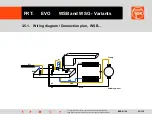
Page 23: ... as these apply to trademarks FEIN retains all powers of disposition such as copying and right of transfer FRT EVO WSB and WSG Variants 23 118 3 5 1 Wiring diagram Connection plan WSB Mains Clamp Grinding wheel X1 W1 W2A W3A W2B W3B X2 br bu bk bk X3 X6 ...

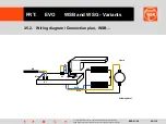
Page 24: ...icular as these apply to trademarks FEIN retains all powers of disposition such as copying and right of transfer FRT EVO WSB and WSG Variants 24 118 3 5 2 Wiring diagram Connection plan WSB Mains Clamp W1 W3A W2B W3B bu br X3 X1 Grinding wheel X6 ...

Page 25: ...powers of disposition such as copying and right of transfer FRT EVO WSB and WSG Variants 25 118 3 6 Safety test final inspection 3 6 1 Safety test WSB 8 115 WSG 8 115 3 6 2 Safety test WSB 13 125 WSG 13 125 3 6 3 Safety test WSG 9 125 WSG 9 70 E 3 6 4 Safety test WSG 13 125 S WSG 13 150 WSG 13 70 E ...

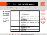
Page 26: ...ting time 3 sec Testing voltage 500 VDC Insulation resistance min 2 0 M Ohm 3 High voltage test 1 Activate 2 Connect L1 and N to plug 3 Switchpad does not have to be pressed through connection exists already Measuring points Gear head and screws 400 320 against L1 N Testing time 3 sec Testing voltage 2500 VAC 4 Trip current 5mA overload relay must not respond 4 Speed test 1 Switch on machine 2 Mea...

Page 27: ...ing time 3 sec Testing voltage 500 VDC Insulation resistance min 2 0 M Ohm 3 High voltage test 1 Activate 2 Connect L1 and N to plug 3 Switchpad does not have to be pressed through connection exists already Measuring points Gear head and screws 400 320 against L1 N Testing time 3 sec Testing voltage 2500 VAC 4 Trip current 5mA overload relay must not respond 4 Speed test 1 Switch on machine 2 Meas...

Page 28: ...on resistance measurement 1 Activate 2 Connect L1 and N to plug 3 Motor switch does not have to be pressed through connection exists already Measuring points Gear head and screws 400 320 against L1 N Testing time 3 sec Testing voltage 500 VDC Insulation resistance min 2 0 M Ohm 3 High voltage test 1 Activate 2 Connect L1 and N to plug 3 Motor switch does not have to be pressed through connection e...

Page 29: ...nsulation resistance measurement 1 Activate 2 Connect L1 and N to plug 3 Motor switch does not have to be pressed through connection exists already Measuring points Gear head and screws 400 320 against L1 N Testing time 3 sec Testing voltage 500 VDC Insulation resistance min 2 0 M Ohm 3 High voltage test 1 Activate 2 Connect L1 and N to plug 3 Motor switch does not have to be pressed through conne...

Page 30: ... 125 4 1 Preparation 4 2 1 Speed control disconnecting 4 2 2 Speed control removal 4 3 Carbon brushes and carbon brush holder 4 4 1 Disassembling the gears 4 4 2 Disassembling the gearbox case 4 4 3 Disassembling the protective cover 4 4 4 Disassembling the gear plate 4 5 Disassembling the armature 4 6 1 Disassembling the field magnet unit pressure plates 4 6 2 Disassembling the field magnet unit ...

Page 31: ...ers of disposition such as copying and right of transfer FRT EVO WSB and WSG Variants 31 118 4 1 Preparation 1 Activate unplug connector Move lever forwards 480 and remove clamping 680 Clamped accessories 2 Unscrew five Ejot PT screws 320 and remove the motor case 265 Tools Phillips screwdriver PH2 1 2 ...

Page 32: ...nd WSG Variants 32 118 4 2 1 Speed control disconnecting 1 Press down unlocking pins and remove power cable strands 290 Remove clamping block from speed controller 80 2 Unfasten Ejot PT screws 180 and cable clamp 160 3 Press down remaining unlocking pins and remove cable strands 230 240 from carbon brush holder 195 and field magnet unit 10 Tools Screw driver 2 5x75 1 2 3 ...

Page 33: ...d WSG Variants 33 118 4 2 2 Speed control removal Tools Screw driver 2 5x75 Bolts M3x18 1 Remove cable strands from strand guide of speed controller 80 2 Insert two M3x18 bolts into the bore holes of the field magnet unit 10 Lightly press the bolts together loosen lock and remove speed controller 3 Unlock ribbon cable plug from switching module 60 and unplug it 1 2 3 4 5 ...

Page 34: ...wn cable strand 230 from carbon brush holder 195 2 Remove carbon brush holder 195 from field magnet unit shaft 15 3 Completely remove carbon brush holder 195 together with black cable strand 240 from field magnet unit 15 4 The carbon brush holders are not all identical The carbon brush holders 195 must be removed before disassembling the armature 750 Otherwise you will damage the armature 750 and ...

Page 35: ...Remove the 4 Ejot PT bolts 810 820 from the field magnet unit 15 4 Screw the two forcing bolts special tool into the threaded bores for handles 830 Using the armature lock special tool fasten the entire armature 750 into the gearbox case 405 5 Lightly tap against the forcing bolts special tool to separate the field magnet unit 15 from the gearbox case 405 6 After removing the armature disassembly ...

Page 36: ...or handles 830 Fasten the threaded bolts special tool into the vice Drive out the bolt 500 using a split pin Remove the lever 480 bolts 430 and cam ring 490 2 Drive out the bushing 470 using a split pin 3 See parts 4 Remove the oval head screw 420 and the fastening spring 410 5 Drive out the needle sleeve 460 using Kukko needle bearing remover and hammer Tools Split pin driver Ø 5 Split pin driver...

Page 37: ...sfer FRT EVO WSB and WSG Variants 37 118 4 4 3 Disassembling the protective cover 1 Using two screwdrivers wedge off the flange 670 2 Remove circlip 660 Parts have been pre tensioned injury hazard 3 Remove spring washer 650 protective cover 640 lever 630 and compression spring 620 Tools 2x slotted screwdrivers 9x150 Circlip pliers straight opener 1 2 3 ...

Page 38: ...530 from the bearing plate 510 using a plastic hammer 2 Using a mandrel press press off the drive shaft 530 from the grooved ball bearing 520 and gear 285 dispose grooved ball bearing 520 afterwards 3 Image Parts 4 Insert pressure plate 560 using a split pin and mandrel press up to limit Wedge out snap ring 570 using a screwdriver 5 Image Parts Tools Plastic hammer Mandrel press Split pin driver Ø...

Page 39: ... it off of the armature 750 3 Remove the grooved ball bearing 800 using the pull off cap special tool and clamping chuck special tool 4 Image disassembled parts 5 Press off the ring magnet 780 and grooved ball bearing 770 using split pin driver and press out plate special tool against mandrel press 6 Image disassembled parts Tools Punch Mandrel press Pull off cap 64104150008 Clamping chuck 26mm 64...

Page 40: ...he field magnet unit pressure plates 1 Gently lift off the pressure plate 95 on gear side at the right using screwdriver and wedge it out by pressing a screwdriver to the right from the left side 2 Remove the pressure plate 95 3 Using a screwdriver wedge the pressure plate 95 mains cable side out of the lock 4 Wedge out the pressure plate fram 95 and pressure plate 95 Tools 2 x slotted screwdriver...

Page 41: ...ield magnet unit switching module 1 Remove the two screws 70 from the switching module 60 2 Lift off the switching module 60 from the field magnet unit 15 3 Insert the spreading tool special tool tightly into the field magnet unit 15 4 Grip the switching module 60 on the gear side and lift it off of the field magnet unit 15 5 Image Parts Tools Phillips screwdriver PH1 Spread out tool special tool ...

Page 42: ...ansfer FRT EVO WSB and WSG Variants 42 118 5 Assembly WSB 13 125 5 1 Gearbox case 1 5 2 Gearbox case 2 5 3 Gear plate 5 4 Protective plate 5 5 Armature new 5 6 Switching module 5 7 Pressure plates 5 8 Armature 5 9 Carbon brushes 5 10 Cable strand placement 1 5 11 Cable strand placement 2 5 12 Case shells 5 13 Bearing plate 5 14 Customer ready assembly ...

Page 43: ...e gearbox case 405 backwards onto the support arrow of the press in tool special tool 3 Insert the cam plate 440 4 Insert ondular washer 450 5 Insert the needle sleeve 460 with the correct position so that it is flush Warm up the gearbox case to 80 100 C The bearing labelling should not be visible when pressed in 6 Image Bearing labelling Tools Press in tool special tool 64114024005 or metal block...

Page 44: ... Firmly insert the forcing bolt special tool tighten the vice Drive the bushings 470 into the gearbox case 405 using a split pin so that they are flush along the sides 4 Lightly grease the bolts 430 and the cam ring 490 Insert the bolts 430 into the gearbox case 405 5 Insert the lever 480 using the cam ring 490 into the gearbox case 405 and drive in the bolts 500 using split pin drivers Tools Spli...

Page 45: ...50 and pressure plate 560 into drive shaft 530 Using the split pin driver and mandrel press Push the pressure plate downwards until it stops Insert snap ring 570 checl position 4 Image Insertion position of snap ring 570 5 Press drive shaft 530 onto grooved ball bearing 520 6 Lay closing plate 580 onto gear 285 Press drive shaft 530 with grooved ball bearing 520 onto gear 285 7 Press 530 up to sto...

Page 46: ...e 510 2 Place lever 630 onto compression spring 620 3 Put on the protective cover 640 4 Place the spring washer 650 on and snap the circlip 660 onto the drive shaft 530 5 Press the circlip 660 together with the sleeve into the seat 6 Orientate the flange 670 with the 2 corners facing the drive shaft 530 7 Press the flange 679 onto the drive shaft 530 adjust and press again if necessary Tools Mandr...

Page 47: ...ved ball bearing 3 Warm up the drive pinion 285 to approx 80 100 C 4 Take up the armature 750 in the press on tool special tool press the drive pinion 285 under the mandrel press 5 Press in the grooved ball bearing 770 6 Press in the ring magnet 780 until it is flush 7 Installation dimension X of ring magnet 780 X for 800 watt 169 3 0 1 mm X for 1200 watt 185 3 0 1 mm Tools Mandrel press Ball bear...

Page 48: ...net unit 15 The cable strand must lie precisely in the prescribed channel arrow 2 Insert the spreading tool special tool tightly into the field magnet unit 15 Set the switching module 60 onto the field magnet unit 15 3 The seals 55 56 must be properly seated 4 Pull the spreading tool special tool out of the field magnet unit 15 5 Fasten bolts 70 of the switching module 60 onto the field magnet uni...

Page 49: ... Assembling the pressure plates 1 Lay the pressure plate 95 gear side diagonally into the field magnet unit 10 and press in the lock 2 Image Properly assembled pressure plate 95 3 Insert the pressure plate 95 electronic side into the field magnet 10 4 Hook the pressure plate frame 95 into the field magnet unit 10 and use a screwdriver to snap it into place Tools Slotted screwdriver 2 5x75 1 2 3 4 ...

Page 50: ...mbling the armature 1 Image Parts 2 Insert the completely assembled armature 750 into the completely assembled gearbox case 405 Hold the gearbox case 40 downwards and using the plastic hammer tap it from the bottom until the armature 750 is properly seated in the bearing 3 Tighten the bolts 820 20 mm in length 4 Tighten the bolts 810 13mm in length Tools Plastic hammer Phillips screwdriver PH2 1 2...

Page 51: ...to the carbon brush slot until it stops 3 Press the flat insertion sleeve 230 brown strands onto the flat connecting tongues on the carbon brush holders 195 using slotted screwdrivers 4 Image Empty carbon brush slot lower side of machine 5 With the black cable strand 240 attached press the carbon brush holder 195 into the carbon brush slot until it stops using a slotted screwdriver 6 Cable strand ...

Page 52: ...Insert the elec speed controller 80 into the field magnet unit 15 and insert the ribbon cable from the switching module 60 into the speed controller 80 2 Insert the speed controller 80 into the field magnet unit 15 until it snaps into place 3 Insert the brown cable strand 230 as shown in the figure 4 Insert the black cable strand 240 as shown in the figure 5 Insert the cable strand as shown in the...

Page 53: ...ts 53 118 5 11 Cable strand placement 2 1 Image Speed controller 80 2 Connect the blue and brown 230 cable strands as shown in the figure see also electrical plan 3 Connect the black cable strands as shown in the figure see also electrical plan 4 Insert the cable strand as shown in the figure Do not solder the cable strands do not use ferrules Tools Slotted screwdriver 2 5x75 1 2 3 4 ...

Page 54: ...er 250 into motor case 265 3 Fasten mains power cable 290 and protective tubing 270 using cable clamp 160 and two bolts 180 Note length of cable ends 65 75 mm Only apply solder to the wire tips do not solder through 4 Fasten the mains power cable 290 to the speed controller 80 5 Insert the previously mounted field magnet unit 15 into the motor case 265 6 Check that the cable strands are properly s...

Page 55: ...pper motor case 265 using 5 bolts 320 18mm in length 2 Fill the gearbox case with 24g WSB or 40g WSG of grease Only apply a small amount of grease to the needle sleeve 460 do not fill 3 The gear tooth flank clearance can be corrected using compensating discs 590 Apply Loctite 573 to both sides of the compensating discs 590 4 5 Insert previously mounted bearing plates 510 and tighten using 4 oval h...

Page 56: ...FRT EVO WSB and WSG Variants 56 118 5 14 Customer ready assembly 1 Check type plate and replace if necessary 2 Image Machine with clamping unit 680 and assembled handle 830 3 Image Machine ready for customer The machine can only be delivered to the customer with the protective cover 640 assembled No other tools may be mounted on the machine Tools None 1 2 3 ...

Page 57: ...se apply to trademarks FEIN retains all powers of disposition such as copying and right of transfer FRT EVO WSB and WSG Variants 57 118 6 Tools for maintenance work 6 1 All mechanical tools 6 2 Special tools 6 3 Lubricants 6 4 Adhesive sealing and other agents ...

Page 58: ... 3 5x80 5 5x100 9x150 Retail Torx screwdriver TX 15 Retail Flat pliers Retail Needle bearing remover Kukko 21 45 Retail Press mandrel Ø19 9x60 Retail Forcing bolt special tool 6 411 40 30 00 0 Armature pinion lock special tool 6 413 10 05 00 5 Press out plate special tool 6 410 20 71 00 8 Spread out tool special tool 6 413 10 06 00 9 Press in tool special tool or metal block 15x30x25 6 411 40 24 0...

Page 59: ...s of disposition such as copying and right of transfer FRT EVO WSB and WSG Variants 59 118 6 2 Special tools 6 2 1 Armature pinion lock 6 2 2 Spread out tool 6 2 3 Forcing bolt 6 2 4 Press out plate 6 2 5 Press in tool 6 2 6 Press on tool 6 2 7 Pipe 6 2 8 Pull out plate 6 2 9 Pull off cap clamping chuck ...

Page 60: ...uch as copying and right of transfer FRT EVO WSB and WSG Variants 60 118 6 2 1 Armature pinion lock 14 0 0 05 4 0 6 0 14 0 0 05 25 0 18 0 60 0 18 0 Special tools For fastening the armature 750 in the gearbox case 405 Tolerances for dimensions with unmarked tolerances 0 2 mm Material Aluminium Article code 6 41 31 005 00 5 ...

Page 61: ...ing and right of transfer FRT EVO WSB and WSG Variants 61 118 6 2 2 Spread out tool R 5 20 0 100 0 52 0 12 0 7 0 7 0 62 0 10 0 2 5 1 0 2 0 38 5 20 0 30 0 36 0 34 0 2x 45 Special tools For spreading out the field magnet unit 15 Tolerances for dimensions with unmarked tolerances 0 2 mm Material Aluminium Article code 6 41 31 006 00 9 ...

Page 62: ...f transfer FRT EVO WSB and WSG Variants 62 118 6 2 3 Forcing bolt Size 12 37 0 9 0 M 8 Ø 14 5 Thread undercut 8 0 Both sides centred on bolt 0 5x45 2 0x45 Special tools Forcing bolt for fastening to the gearbox case 405 Quantity 2 Tolerances for dimensions with unmarked tolerances 0 2mm Material St 37 Surface gunmetal Article code 6 41 14 030 00 0 ...

Page 63: ...ight of transfer FRT EVO WSB and WSG Variants 63 118 6 2 4 Press out plate Special tools for pressing out grooved ball bearings 770 and ring magnets 780 Tolerances for dimensions with unmarked tolerances 0 2mm Material Sb 4 5 case hardened steel nitrided Article code 6 41 02 071 00 8 10 0 12 5 18 0 20 0 11 0 16 0 20 0 20 0 100 0 100 0 t 4 0 ...

Page 64: ...in particular as these apply to trademarks FEIN retains all powers of disposition such as copying and right of transfer FRT EVO WSB and WSG Variants 64 118 Press in tool For pressing in needle sleeves 460 6 41 14 024 005 6 2 5 Press in tool ...

Page 65: ...ply to trademarks FEIN retains all powers of disposition such as copying and right of transfer FRT EVO WSB and WSG Variants 65 118 Press on tool For securely fastening armature 750 6 41 01 019 008 108 0 8 0 13 0 Ø 7 1 Ø 36 1 Ø 45 0 point welded 6 2 6 Press on tool ...

Page 66: ...IN in particular as these apply to trademarks FEIN retains all powers of disposition such as copying and right of transfer FRT EVO WSB and WSG Variants 66 118 Pipe Can be placed on pull out plate 6 41 01 002 00 4 6 2 7 Pipe Ø 129 7 Ø 120 ...

Page 67: ... FRT EVO WSB and WSG Variants 67 118 6 2 8 Pull out plates Pull out plate For pulling out bevel drive of armature 285 WSB 8 115 WSB 13 125 WSG 8 115 WSG 13 125 WSS 12 125 6 41 02 069 007 Pull out plate For pulling out bevel drive of armature 285 WSG 9 125 WSG 13 150 WSG 13 125 S WSG 9 70E WSG 13 70E WSG 12 125 150 WPO FSs 12 27E 6 41 02 067 005 Not for WSB ...

Page 68: ...sition such as copying and right of transfer FRT EVO WSB and WSG Variants 68 118 6 2 9 Pull off cap clamping chuck Clamping chuck For clamping grooved ball bearing 800 Clamping chuck 26mm 800 6 41 07 026 00 0 Pull off cap For pulling off grooved ball bearing 800 with the help of the clamping chuck 6 41 04 150 00 8 ...

Page 69: ...nge 30 C to 120 C Normally loaded spur gear and roller bearing also slide bearing with higher speed 85g tube 3 21 600 0301 4 800g tin 3 21 320 070 1 4500g tin 3 21 320 1001 5 Gears 405 24g For WSG 13 150 40g 0 40 106 0100 1 old Sst6 Drop point approx 190 C Temperature range 60 C to 130 C Roller bearing grease Highest speed roller bearings Neutral against E and NE metals and resistant plastics PA P...

Page 70: ...e best gap 0 05 mm max 0 12 mm for threads M16 fine thread M36 55C to 150C hand tight 15 30 min final tightness 3h storage time min 12 months For all types of plastic joints 04800500027 04800500011 Loctite 573 green 250ml 50ml Slow curing easy to disassemble very resistant against loads and vibrations For sealing flange joints on gear and motor casings differential casings bearing covers etc Hand ...

Page 71: ...WSG Variants 103 118 7 Modifications extras information for maintenance and repair technicians 7 1 Differences between types WSB 8 115 and WSB 13 125 7 2 Differences between types WSB 8 115 and WSB 13 125 7 3 Modifications extras information for the maintenance 7 4 Modifications extras information for the maintenance 7 5 Modifications extras information for the maintenance ...

Page 72: ...1 Differences between types WSB 8 115 and WSB 13 125 WSB 8 115 Motor casing 265 approx 245 mm long WSB 13 125 Motor casing 265 approx 265 mm long WSB 8 115 Field magnet of field magnet unit 15 approx 35 mm long WSB 13 125 Field magnet of field magnet unit 15 approx 55 mm long WSB 8 115 Metal sheathing for armature 750 approx 35 mm long WSB 13 125 Metal sheathing for armature 750 approx 55 mm long ...

Page 73: ...demarks FEIN retains all powers of disposition such as copying and right of transfer FRT EVO WSB and WSG Variants 105 118 7 2 Differences between types WSB 8 115 and WSB 13 125 WSB 8 115 Switching module 60 approx 190 mm long WSB 13 125 Switching module 60 approx 210 mm long ...

Page 74: ... controller type plate Machine type plate 1 Company logo 2 Material no 3 Country of manufacture and manufacturer s address 4 Symbol safety class II 5 Warning symbol Read documentation 6 European mark of conformity 7 Warning symbol Wear eye protection 8 Prohibitory sign Do not dispose with domestic waste 9 Year of manufacture month of manufacture serial production number in month of manufacture 10 ...

Page 75: ... such as copying and right of transfer FRT EVO WSB and WSG Variants 107 118 7 4 Modifications extras information for the maintenance Switching module type plate Article code Switching module Production date Switching module type L length 1200 watt K short 800 watt S 5 5 occupied keys S 4 4 occupied keys V variable speed ...

Page 76: ...sfer FRT EVO WSB and WSG Variants 108 118 7 5 Modifications extras information for the maintenance Production start 02 2004 WSB 8 115 WSB 13 125 WSG 8 115 WSG 13 125 07 2004 WSG 9 125 WSG 13 150 03 2005 WSG 13 125 S 11 2005 WSG 13 70E 12 2005 WSB 8 115 WSB 13 125 dead man model without lock on switch Difference Cover 250 between motor cases 265 is black ...

Reviews: