IDENTIFICATION
ID CPR60
Page 21 of 22
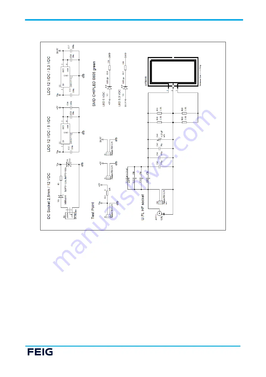
Figure 9: CPR60-DevBoard Schematic Part 2
Page 1: ...IDENTIFICATION M91210 3e ID B Ende der Liste f r Textm arke Deckbl att INSTALLATION MANUAL ID CPR60 RFID Reader Module Model Article No ID CPR60 A 5491 000 00...
Page 2: ...y not be completely avoided we are always grateful for your useful tips The instructions given in this manual are based on advantageous boundary conditions FEIG ELECTRONIC GmbH does not give any guara...
Page 3: ...6 2 3 Development Board 6 3 Dimensions 7 4 Installation and wiring 8 4 1 Connector X1 8 4 2 Connector ANT 11 5 Standby Low Power Card Detection 12 6 Technical Data 13 7 Radio Approvals 15 7 1 Declara...
Page 4: ...ce or for an incorrect application of a device Repairs may only be executed by the manufacturer Installation operation and maintenance procedures should only be carried out by qualified personnel Use...
Page 5: ...nown CPR family like the reader module ID CPR74 or the wall mount reader ID CPR50 10 and is compatible with them mainly The use of ISOHost commands guarantees an easy creation of user software as well...
Page 6: ...and antenna is available on request see Available Accessories The ID CPR60 DevBoard offers 3 SAM sockets for ID 000 smart cards 1 smart card connector for full size ID 1 cards and different connectors...
Page 7: ...N ID CPR60 Page 7 of 22 3 Dimensions The ID CPR60 reader module has been designed for the integration into terminals printers or handheld devices and so on Figure 1 Dimension Top View Figure 2 Dimensi...
Page 8: ...following table shows the pin assignment of the connector Interfaces and functions are described from the ID CPR60 view an input must be connected to one output or vice versa Figure 3 Connector X1 At...
Page 9: ...K SAM4 18 n c 19 SAM1_I O 20 n c 21 SAM2_I O 22 n c 23 SAM3_I O 24 n c 25 KCC_I O SAM4 26 SAM1_VCC 27 n c 28 SAM2_VCC 29 n c 30 SAM3_VCC 31 n c 32 GND 33 n c 34 KCC_VCC SAM 4 35 GND 36 SAM1_CLK 37 SPI...
Page 10: ...M 4 54 n c 55 GND 56 n c 57 n c 58 GND 59 n c 60 5 V DC Supply 61 n c 62 n c 63 n c 64 nRESET Reset Input 65 RS232_TxD reader TxD host RxD 66 RS232_RxD Reader RxD Host TxD 67 n c 68 n c 69 n c 70 n c...
Page 11: ...escription and hints for building external 50 antennas can be taken from the application note N20901 d ID B pdf NOTICE Only for use with 50 matched external antennas The permanent usage of unmatched a...
Page 12: ...y mode is activated if input nLOW_PWR is set to low In this mode the reader wakes up if a contactless card is detected in front of the RFID antenna or if the Input nKCC_DET is set to 0 The reader rema...
Page 13: ...sumption 400 mA without SAM 25mA Standby mode 50mA Standby Mode with Wake Up by Card Interfaces USB Full Speed 12 Mbit s Self Powered Device SPI Slave Device up to 16 Mbit s RS232 LVTTL 4 800 921 600...
Page 14: ...Power Class A B C Operating Modes ISOHost Mode Polling Mode Radio Approval Europe UK USA Canada EN 300 330 EN 300 330 FCC Title 47 CFR Part 15 RSS 210 Issue 10 RSS Gen Issue 5 incl Amendment 1 EMV EN...
Page 15: ...ty is available at the following internet address https www feig de en service eu declarations of conformity 7 2 Declaration of Conformity UKCA UKCA Declaration of Conformity Hereby FEIG ELECTRONIC Gm...
Page 16: ...toris e aux deux conditions suivantes 1 l appareil ne doit pas produire de brouillage et 2 l utilisateur de l appareil doit accepter tout brouillage radio lectrique subi m me si le brouillage est susc...
Page 17: ...ystem must be professionally installed to ensure compliance with the Part 15 certification IC certification It is the responsibility of the operator and professional installer to ensure that only cert...
Page 18: ...IDENTIFICATION ID CPR60 Page 18 of 22 8 ANNEX 8 1 Annex A ID CPR60 DevBoard Reference Design Figure 5 Top Overlay Print Figure 6 Top Layer...
Page 19: ...IDENTIFICATION ID CPR60 Page 19 of 22 Figure 7 Bottom Layer...
Page 20: ...IDENTIFICATION ID CPR60 Page 20 of 22 Figure 8 CPR60 DevBoard Schematic Part 1...
Page 21: ...IDENTIFICATION ID CPR60 Page 21 of 22 Figure 9 CPR60 DevBoard Schematic Part 2...
Page 22: ...Horizontal J8 Pin header 5 poles RM2 54 Horizontal KCC SAM 4 SMD Smart Card Connector ID1 8 Pin R1 SMD resistor 100K0 0 125W R16 SMD resistor 220R0 0 125W R17 SMD resistor 100R0 0 125W R3 R4 R11 R12 R...