OBID i-
scan
®
Installation
ID ISC.MR100-A / PR100-A
FEIG ELECTRONIC GmbH
Page 30 of 39
M10202-3de-ID-B.doc
E N
G
L I S H
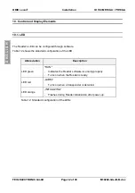
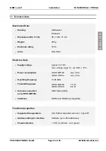
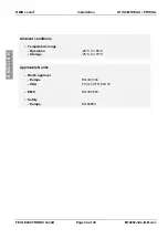
In the case of the RS485 configuration, the termination resistors which may be required can be
inserted using jumpers
J73
,
J74
and
J77
.
Jumper
in
out
J73
Pull-Up on RS485 - B
out
Pull-Up on RS485 - B
J74
Pull-Down on RS485 - A
out
Pull-Down on RS485 - A
J77
Termination resistor
RS485 - A
⇔
RS485 - B
no
termination resistor
RS485 - A
⇔
RS485 - B
Table 9: Configuring the RS485 interface
J73
J77
J74
RS485 - B+
RS485 - A-
Fig. 2: Jumper of the RS485 interface
9.6.2. RS232 interface
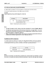
The RS232 interface is connected through X2.
The transmission parameters can be configured using software protocol.
Pin assignments X2 (RS232 interface):
Terminal
Abbrev.
Description
2
TxD
RS232 – TxD
3
RxD
RS232 – RxD
5
GND
RS232 – GND
Table 10: Wiring assignments for the RS232

