background image

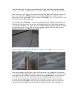
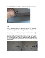
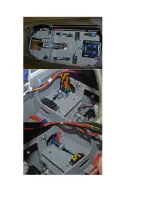
Cover the underside of the elevator directly behind the elevator servo horn position with masking
tape, then use a ruler or straight edge to draw a line across the elevator in line with the servo horn.

Draw a second line 5mm outboard of the previously drawn line – this is the centre line of the slot for
the elevator control horn. Offer the elevator horn into place, and position it so that the control
linkage hole in the horn is directly over the hinge line of the elevator – mark the front and rear of the
base of the horn onto the masking tape.

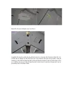
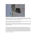
Very carefully use a suitable diameter router bit in a Dremel or similar high speed multi tool to cut a
slot along the line drawn from the servo horn, and between the front and rear marks made earlier –
use eye protection! Open up the hole to the correct width and depth using Permagrit files – be VERY
careful to clean out the slot only as far as required and make sure not to cut into the inside of the
top skin of the elevator, do NOT break through the skin.

Check the fit of the control horn into the slot, when happy use Permagrit or coarse sandpaper to
roughen the base of the control horn.

Remove the masking tape left on the elevator from the previous steps and then use four separate
pieces of tape along the edges of the slot, leaving around a 1mm gap. Glue the horn into place in the
slot using Hysol or Deluxe Materials AeroTech adhesive, ensuring adequate glue is used, then make
sure that the horn is in the exact position required, wipe off the excess glue, and remove the
masking tape protecting the paint finish before the Hysol begins to cure, which would make the
masking tape almost impossible to remove cleanly. Recheck the position of the horn, then put to
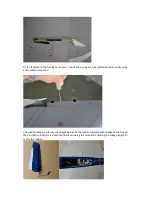
one side until the Hysol is fully cured. An example of a typical horn installation is shown below.

Summary of Contents for hawker hunter

Page 1: ...depending on the turbine being used the on board radio equipment batteries being used etc that the model will probably weigh more than 20Kg without fuel or 25 Kg with fuel and that certain countries h...

Page 2: ...with great success Servos The Hunter requires a total of 7 high quality servos for the flying surfaces and a further metal geared high power servo for nose wheel steering The prototype model used meta...

Page 3: ...slot neatly Fit the elevator servo to the hatch making sure all screws are completely tight Fit a suitable length extension lead to the elevator servo it is highly recommended that a heavy duty lead...

Page 4: ...nd depth using Permagrit files be VERY careful to clean out the slot only as far as required and make sure not to cut into the inside of the top skin of the elevator do NOT break through the skin Chec...

Page 5: ...or full and free travel making sure that the servo arms or pushrods cannot jam in any position It may be necessary to bend the pushrods slightly to allow adequate clearance to the end of the slots in...

Page 6: ...tightened and consider using a threadlock compound The rudder linkage is internal see photos below Fit the rudder complete with linkage to the fin and then install the rudder servo as show finally cen...

Page 7: ...allen screws used on the landing gear units and oleo legs are checked use of a threadlocking compound on all these screws is suggested whilst the landing gear is removed from the model Fit extension...

Page 8: ...three air ram operated doors these all remaining open the entire time that the retracts are extended Forward Fuselage Initial Assembly Remove the nose retract unit in the similar manner to the mains...

Page 9: ...orward fuselage back to the wing mount area and the rear for connection to the tailplane and rudder extension leads Assemble the fuel tanks check for leaks and then check that they fit correctly into...

Page 10: ......

Page 11: ...embled due to lack of access The extension leads for the rudder and tailplane servos should be retained to the fuselage sides so that they are well away from the tailpipe using commercial servo lead m...

Page 12: ...Fit the mounting lugs to the bellmouth section of the tailpipe and slide the tailpipe into the rear section of the fuselage...

Page 13: ...elage and then offer up the turbine being used and carefully position this ensuring the turbine manufacturer s recommendation as to the correct gap between the rear of the turbine and the front of the...

Page 14: ...for the screws then fit these screws to secure the tailpipe Fit all remaining extension leads and electrical cables including those for the wing connections the following photo shows a typical connect...

Page 15: ...d cutting it down to suitable length to allow for installation Continue the installation of the remaining on board equipment the prototype used a PowerBox Royal SRS twin receiver battery system being...

Page 16: ......

Page 17: ...as possible a former can be glued into place in the forward fuselage as shown and a battery plate made up that slots into this and which is retained at the rear with a couple of bolts glued through t...

Page 18: ...If the Sabrinas are to be fitted the areas of fuselage that these are glued to should have the paint removed as should the base of the Sabrinas before they are carefully glued into place...

Page 19: ...by an electric actuator or air ram this prototype using the air ram method with a simple bellcrank arrangement to increase the travel to the required amount A cross beam system was used to equalise th...

Page 20: ...d forward through the access provided by the open canopy until the pins come free of the holes and then the rear of the scale cockpit can be dropped before this can be carefully withdrawn through the...

Page 21: ...y out any required trimming then use the remainder of the first flight to get comfortable with the flying characteristics and the slow speed handling trying out the effects of flap deployment Keep a r...

Reviews: