background image

 
I have used SWB alloy arms for all of the flying surfaces to increase the integrity 
of all the controls. They are 25mm arms which is ample for the amount of 
movement you need. 
 
I have tried to arrange a construction sequence that will allow you to keep moving 
forward, rather than standing around waiting for glue to dry before you can 
proceed to the next steps 
 
 
  Introduction: 
 
You have chosen a model that represents the pinnacle of ARF technology. While 
there is not a lot of building to do, there is enough to keep you busy for a many 
hours. Even if you have assembled other ARF jets, we highly recommend 
following our assembly sequence and procedures anyway. Chances are it will 
save you a lot of time, prevent you from running down dead ends, and perhaps 
remind you of a few small things that might end up saving your aircraft.  
 
Just because the model is almost completely built does not mean you can rush 
through the assembly. You need to employ fine craftsmanship every step of the 
way, turbine models need critical care and attention. 
Keep this in mind with everything you do, every part you install...look at the work 
you just did, evaluate it critically, and ask yourself "is this going to potentially 
crash my airplane?" If there is any doubt about the work you have done, back up, 
and re-do it properly.  
 
Adhesives: The correct adhesive to use for all procedures is Loctite Hysol 9462. 
This is a very strong white epoxy that is thixotropic. "Thixotropic" means it does 
not run at all, but stays only where you put it. It is infinitely superior to regular 
epoxy, even slow-setting epoxy, for our purposes, because of this characteristic. 
Regular epoxy will run downhill with gravity as it dries, taking it away from where 
it is intended to be. 
A good example is in the hinges...using regular epoxy, a good portion of the glue 
will migrate down away from the hinge into the inside of the wing as it dries, and 
you won't even know it is happening. Hysol stays where you put it. The downside 
of Hysol is it takes overnight to dry properly, but I have tried to arrange things to 
keep you busy while waiting for glue to dry. I also highly recommend that you only 
use a proper Hysol dispensing gun with the long-type mixing nozzles. 
The short nozzles do not mix this glue enough and only a thin nozzle and gun will 
let you fill the hinge and control horn holes properly with glue, you can't do it 
mixing your Hysol on a flat surface and trying to get the glue in the proper place 
by a brush or stick. 
You can buy a complete Hysol setup including a mixing gun, nozzles and 
cartridges of glue from your local hobby supplier. Consider it a great investment, 
the glue is the best you will use. Two cartridges will be plenty to assemble your 
EF2000 


Summary of Contents for EF2000

Page 1: ...The following instructions are developed based on a Kingtech K140 turbine Spektrum powerbox and Spektrum and JR radio Think of the build as working from the back to the front which makes it seem easie...

Page 2: ...ssembly This is advisable during the build to use the inspector who will do the final turbine inspection A second set of eyes may spot a problem you may have missed If you have not flown a model like...

Page 3: ...1 x brake valve 1 x retract valve 1 x bag of air Y connectors 1 x bag of 4 way air connectors 1 x bag of fuel Y connectors 1 x bag of fuel plugs 7 x servo linkages 2 x small air tanks 2 x large air t...

Page 4: ...Servos used in this build Elevons x 2 JR 8711 24kg Canards x 1 JR 8711 24kg Rudder x 1 JR 8411 12kg Leading edge slats x 4 Spektrum 6020 10kg Steering x 1 JR 8231...

Page 5: ...have done back up and re do it properly Adhesives The correct adhesive to use for all procedures is Loctite Hysol 9462 This is a very strong white epoxy that is thixotropic Thixotropic means it does...

Page 6: ...t you can add fine wire safety wraps if you like Make sure all left and right matching airlines are the same length particularly the brake lines or you will get uneven retraction or braking action It...

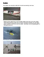
Page 7: ...ecured by 4 screws Rough up the rudder horns and check the depth where they sit on the rudder Check the positioning as the hole in the horn should be directly over the hinge point Hysol the control ho...

Page 8: ...e 3mm bolt at the front of the rudder Feed the wires for the servo to the hole provided that goes through the fuselage Note the hole below the rudder on the fuselage is another 3mm mounting bolt for t...

Page 9: ...Use an incidence meter to guide where you set the canards Check the wings and then set the canards at the same angle This will be very close for the test flight...

Page 10: ...o be longer Hysol the horn in place after roughing the surface you may need to increase the depth of the hole to get the correct position of the horn Measure the position so the hole in the horn is di...

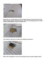
Page 11: ...o to the hatch with the countersunk 3mm screws This is the leading edge slat one below but the same method is used on all the servos Use Loctite on all screws to make sure nothing comes loose Bolt on...

Page 12: ...0 12 kg servos Use the same method to mount the servos with the plastic mounts provided I used heavy duty nylon servo arms and cut them off short The room is limited in this area so trial fit everythi...

Page 13: ...Where possible I used rubber grommets to protect the servo wiring Enlarge the holes where the grommets sit for a good fit...

Page 14: ...Screw the covers provided to the wings to cover the servo arms and linkage The end where the surface moves will need to be cut and made a separate piece...

Page 15: ...not add the tanks and rockets until after I did the test flight This was to ensure that the weight and drag of the model wasn t too great The wing tanks mount with a 3mm socket head bolt on one end Y...

Page 16: ...uel pump and valves so they sit under the ducting Plastic clips keep airlines fuel lines and extension leads neat and safe from excessive heat or kinking All the doors need to remain open when the whe...

Page 17: ...1 digital as it s important to use a positive centering digital servo particularly because of the length of the nose You will have to put small amounts of movement on the nose wheel to be practical Th...

Page 18: ...Trim all the ducting to fit around the intakes and allow for easy maintenance if things need to be removed...

Page 19: ...provided Add the detail pieces to the rear and underside The piece shown below mounts with a 3mm bolt too I used Hysol to mount both pieces This piece is glued with Hysol to the bottom of the fuselag...

Page 20: ...the exhaust nozzles Test fit the exhaust pipe to check for length this will determine where the turbine mounts Ensure you mount the turbine as far forward as possible Leave a 10 15mm gap between the...

Page 21: ...the rear of the engine mount leaving the tailpipes 10mm inside the nozzles The pipe setup aids with the cooling and performance of your turbine Optimal distance between the tailpipe of the turbine and...

Page 22: ...s as well This keeps the entire set up mounted solidly Test fit the turbine and fit blind nuts under the rails Also use the countersunk screws so they are flush I put all the 3mm screws in the wing mo...

Page 23: ...e is mounted complete the wiring for the computer fuel lines and valves When the ducting and wiring is complete clip up all wires where possible The ducting will need trimming to suit your turbine I m...

Page 24: ...I used Dubro tanks one 1900ml and 2 x 750ml Use Festo 4 6mm fittings for all the connections They seal well and make it possible to do maintenance easily The brass tube supplied works perfectly with 4...

Page 25: ...irtanks Airtanks Airtanks Airtanks I paired the 2 large tanks for retracts and doors The 2 smaller ones operate the brakes The 2 smaller tanks went on the underside of the tray and the large on the to...

Page 26: ...ctory installed removable nose section which makes mounting the batteries very simple I made a removable tray for both the batteries for the flight system Mount the nosecone with the 4 x 3mm bolts usi...

Page 27: ...the wheels doors and wheel brakes This makes for a neat installation because of its simplicity After all the nose section and fuel tanks are finished the next step is to complete a tray for the start...

Page 28: ...side Once all the wiring air hoses and fuel lines are complete check the fit of the rear hatch The 2 piece detailed cockpit needs to be fitted so that removing it when the canopy to access all the bat...

Page 29: ...n 20 expo Canards 20mm up and down 25 expo Rudder 30mm left and right 20 expo Nose wheel servo 10 15 degrees movement with 15 20 expo C G 330mm from leading edge at the root of the left wing with the...

Reviews: