background image


- 23 -

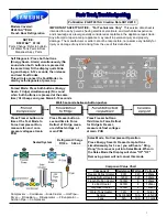
Pre-Service Checklist 

You may avoid the cost and inconvenience of an unnecessary service call by first reviewing this 
checklist of frequently encountered situations that can cause unsatisfactory case performance. 


CAUTION: 

Before servicing case turn off power at the main breaker of fuse 
box. 


Case Does Not Operate 


-Check for disconnected power supply. 


-Check for tripped breaker or blown fuse. 


-Check that power switch is on. 


Lights Do Not Operate 


-Check that light switch is on. 


-Be sure light is properly seated in the sockets. 


If supplied with shelf light option 
-Check that shelf light cord(s) are tight in the sockets. 


-Plug unused light sockets with socket cap provided with socket. 


Case Temperature Too Warm 


-Check that the cold air inlet and outlet slots are not blocked. 


- If supplied with rear door option be sure that the rear doors are closed and tightly sealed. 


-Check for a blocked or dirty condenser coil fins. 
-Check cold airflow.  Lack of adequate cold airflow could be a defective evaporator fan or 
   blocked evaporator coil.  Check that paper or foreign material is not blocking evaporator. 
  If the evaporator coil is blocked due to excessive frost, turn the power switch “off” position  
  for approximately one hour to defrost.   


-Check that the display pan(s) are installed properly. Slots must be towards the front and is 
   marked front 


-Is the case installed properly to allow adequate air flow to and from condenser. 


Special Service Situations 

There are rare occasions when the refrigerant charge must be evacuated from a case in order to 
perform service work.  In those situations, Federal Industries recommends that the refrigerant 
charge be evacuated into a recovery system to prevent the possibility of hydrofluorocarbons 
(HFC’s) from being released into the atmosphere. 


If moisture or liquid is observed around or under a Federal Industries case, an immediate 
investigation should be made by qualified personnel to determine the source of the moisture or 
liquid.  The investigation made should determine if the case is malfunctioning or if there is a simple 
housekeeping problem. 


Moisture or liquid around or under a case is a potential slip/fall hazard for persons walking by or 
working in the general area of the case.  Any case malfunction or housekeeping problem that creates 
a slip/fall hazard around or under a case should be corrected immediately. 


Summary of Contents for LPRSS-2

Page 1: ...STRUCTIONS REFRIGERATED LPRSS 2 MODELS KEEP THIS MANUAL FOR FUTURE REFERENCE Engineering and technical data are subject to change without notice FEDERAL INDUSTRIES 215 FEDERAL AVE Belleville WI 53508...

Page 2: ...STIC END REMOVAL INSTALLATION 13 REAR DOORS OPTION 12 NIGHT CURTAIN OPTION 14 SECURITY NIGHT COVER OPTION 15 OPERATING INSTRUCTIONS 16 User Controls 16 Temperature Control Function 17 Initial Start Up...

Page 3: ...g components contain technical instructions intended only for persons qualified to perform electrical work DANGER Improper or faulty hookup of electrical components in the case can result in severe in...

Page 4: ...r death will occur if you ignore the message WARNING Severe injury or death can occur if you ignore the message CAUTION Minor injury or damage to your case can occur if you ignore the message NOTICE T...

Page 5: ...irements of the case See the electrical data plate located on the rear left interior of the case for the proper circuit size for each case The cord is factory installed protruding from the bottom rear...

Page 6: ...reakage could result 1 Remove crate top and sides and note missing or damaged items as explained in the pre installation procedures outlined above 2 Move the case as near as possible to the final loca...

Page 7: ...se compartment of left case 4 Push the cases together as tightly as possible and the gap between the cases must be tight and even If the gap is larger at the top or the bottom adjust leg levelers acco...

Page 8: ...refrigerant solenoid valve Installation must be performed by a licensed Refrigeration Technician See the Service section of this manual for installation requirements Evaporater Condensate Drain Tube...

Page 9: ...eat energy to remove condensate run off from evaporator coil a condensate pump pumps the water to a nearby drain The Condensate Pump is provided with 50 of clear 1 2 OD x 3 8 ID tubing that must be ru...

Page 10: ...ed shelf standard slot 2 Lift shelf bracket top hook to allow shelf bracket bottom tab to clear shelf standard slot 3 Swing shelf bracketbottom tab into shelf standard slot 4 Place the desired shelf b...

Page 11: ...e located on flat side of glass shelf retainer Position the glass shelf retainer in the 2 far corners of glass as shown in detail drawing above Repeat for each glass shelf NOTE Clean area of glass whe...

Page 12: ...g used for a shelf light the cap must be plugged into socket for entire light system to operate 5 Plug in each shelf light by aligning the male pins on the appropriate shelf light cord plugs with the...

Page 13: ...4 screws in case INSTALLATION 1 Hold panel tightly against the side of the case with the front lip of panel tight against front of case 2 Slide panel forward about until screws fall into key slots Sli...

Page 14: ...s the top of case and down the front 2 Attach the snap located under the night curtain strap on to the snap located on the front trim CLOSING 1 Grab the night curtain strap and detach the snap from th...

Page 15: ...front trim 3 Set the top flange of the security cover down against the top panel 4 Turn the lock handle so it engages the lock handle catch and use key to lock it in place Note The 6 models have 2 sec...

Page 16: ...ire unit including the condensate evaporator and the lights This switch is located behind a lift up panel on the unit base Light Switch The unit has a light switch that turns on and off the interior l...

Page 17: ...environment Alarm light This light indicates that there is a problem with case or electronic control and service should be called Initial Start Up After all the checks outlined in the installation se...

Page 18: ...isplay deck is removable for cleaning and can become dislodged in shipment To ensure proper airflow and performance of the case make sure that the display deck is pushed completely down Allow refriger...

Page 19: ...lb is secure in bulb receptacles Note Be sure to use a direct equivalent to the original bulb PERIODIC MAINTENANCE Cleaning Condenser Coil All Self Contained Refrigerated Units It is very important th...

Page 20: ...foreign material buildup perform the weekly cleaning instructions 1 If Supplied With Optional Rear Doors Clean all foreign materials from the door opening and clean both sides of the doors with a damp...

Page 21: ...tor fan shroud and slide the front lip out of the fan shroud retainer Reach in and unplug the evaporator fan motor cord Remove evaporator fan shroud 7 Clean the entire interior of the case using warm...

Page 22: ...you sell or give away your Federal Industries case and you evacuate the refrigerant charge before shipment Federal Industries recommends that the charge be evacuated into a recovery system to prevent...

Page 23: ...locking evaporator If the evaporator coil is blocked due to excessive frost turn the power switch off position for approximately one hour to defrost Check that the display pan s are installed properly...

Page 24: ...The temperature control sensor is located inside the center tower at the top The sensor location is critical for proper operation on the unit Do not move or relocate this sensor The coil sensor is str...

Page 25: ...or Sensor SET POINTS 8 Cut In Warm 14 F 38 F 9 Cut Out Warm 4 F 28 F 10 Cut In Cold 2 F 38 F 11 Cut Out Cold 16 F 13 Comp Minimum On Time 1 min 5 min 0 sec DISPLAY 15 Defrost Display Lock display indi...

Page 26: ...d initiates a pump down cycle This will allow the remote low pressure switch to open and shut off remote compressor The condensing unit and pressure controls are optionally supplied from the factory f...

Page 27: ...n the data plates REMOTE HIGH LOW PRESSURE CONTROL LIQUID LINE SUCTION LINE INSULATED REMOTE CONDENSING UNIT EVAPORATOR COILS DISPLAY CASE EXPANSION VALVE HIGH LOW LIQUID LINE SOLENOID VALVE SIGHT GLA...

Page 28: ...SSOR Y G BRW G GREEN DEFROSTPROBE REMOTE BLK G LAMP TOP LIGHT LAMP BLK B R B R BLK G SHELF LIGHT LAMP BLK B R B R B R G G SHELF LIGHT B R G W COLOR CODE B BLUE Y YELLOW W WHITE R RED BLK BLACK G GREEN...

Page 29: ...t on Rem 41 11628 Condensate Base Fan Blade Opt on Rem 72 32507 Condensate Pan Ass y Std 3 4 SA5202 Condensate Pan PTC Heater 40 19498 Condensate Pan Wick 15 19469 Condensate Drain Tube 06 17699 SA521...

Page 30: ...67 7A Shelf Bottom Stainless Optional M15967 2A M15967 4A M15967 6A M15967 8A Glass Shelf Top Optional 52 17991 1 52 17991 2 52 17991 3 52 17991 4 Glass Shelf Bottom Optional 52 17992 1 52 17992 2 52...

Reviews: