25500431
Rev. A1 0218
Printed in U.S.A.
© Copyright 2018 Federal Signal Corporation
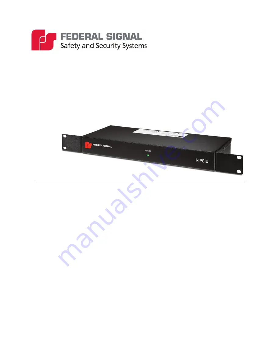
Informer
™
Sensor/Radio Interface Unit
Model I-IPSIU
Description, Specifications,
and Installation Manual
Page 1: ...25500431 Rev A1 0218 Printed in U S A Copyright 2018 Federal Signal Corporation Informer Sensor Radio Interface Unit Model I IPSIU Description Specifications and Installation Manual ...
Page 2: ...y is in lieu of all other warranties express or implied contractual or statutory including but not limited to the warranty of merchantability warranty of fitness for a particular purpose and any warranty against failure of its essential purpose 2645 Federal Signal Drive University Park Illinois 60484 3617 www fedsig com Customer Support 800 548 7229 1 708 534 3400 Technical Support 800 524 3021 1 ...
Page 3: ...tput Locations 9 Visual Indications 10 Ethernet Port PoE 10 Power Input 10 Serial Port 10 Carrier Detect Rear Input 10 Digital Inputs 10 Relay Outputs 10 Audio Input 11 Radio and Audio PTT Outputs 11 Radio Connections 11 Specifications 13 Electrical Code Compliance 14 Installation 14 Determine a Suitable Location 14 Rack Mounting 14 Wall Mounting 15 Testing and Training 16 Replacement Parts 17 Get...
Page 4: ...rical 13 Table 7 Audible Indications 13 Table 8 Serial and Ethernet Ports 13 Table 10 Digital Input 13 Table 11 Relay Output 13 Table 12 Environmental and Physical 13 Table 13 Replacement Connectors Part Numbers 17 Table 14 Scrolling Message Display Part Number 17 Figures Figure 1 I IPSIU Front Views 9 Figure 2 I IPSIU Back View 9 Figure 3 Attach Bracket 14 Figure 4 Rack Mount Dimensions 15 Figure...
Page 5: ...e meaning of warning sounds Users should follow FEMA recommendations and instruct those to be warned of correct actions to be taken After installation service or maintenance test the system to confirm that it is operating properly Test the system regularly to confirm that it will be operational in an emergency Safety Messages to Installers People s lives depend on your safe installation of our pro...
Page 6: ... instructions to all personnel responsible for operation periodic testing and maintenance of the equipment File these instructions in a safe place and refer to them when maintaining and or reinstalling the device Failure to follow all safety precautions and instructions may result in property damage serious injury or death Installation and Service After installation or service test the system to c...
Page 7: ...orbell wires wires from transformers to neon signs steam or hot water pipes and heating ducts Do not place Ethernet wiring or connections in any conduit outlet or junction box containing high voltage electrical wiring Symbol Definition _A _V Indicates to reduce the risk of fire replace fuse as marked Pay careful attention to the notice located on the equipment Read and understand the information c...
Page 8: ... a mobile or portable radio for broadcast of alert messages over the radio system The I IPSIU has carrier detect capability to delay broadcast until the radio system is idle Broadcasts can be pre programmed tones digital voices messages or live PA broadcast A single alert or activation can activate multiple I IPSIUs in support of multi site notifications thereby making it the ideal solution for la...
Page 9: ... Commander network servers for reliable fail safe operation with full two way control status monitoring and configuration of the I IPSIU Optional Features You can order the following accessories separately Scrolling message display part number I SMD2 36 See Table 14 Radio Interface Cables The Universal Cable Adapter is provided with each I IPSIU Find the proper cable for your radio system and orde...
Page 10: ...ons have been made The center connector connects to the positive lead on the DC supply Serial Port The RS232 Port uses a 6 pin modular connector Use the serial port to interface a message board Carrier Detect Rear Input The Carrier Detect Rear Input is used when the radio system provides a contact closure for carrier detect Table 2 Carrier Detect Rear Input Terminal Description 1 and 2 Input from ...
Page 11: ...hese relays are used to active the push to talk PTT on the radio equipment Audio Out Adjust The audio output level is adjustable from 0 to 2 5 Vp p into 600 ohms with 1 kHz tone A removable eight position connector is located on the rear of the I IPSIU for making electrical connections The connector accepts 5 mm 3 16 in stripped wire 18 26 AWG Make electrical connections to the Input Output connec...
Page 12: ...73A Motorola HT 1000 XTS 5000 864700074A Kenwood TK2170 TK2302V NX 240V NX 340U 864700075A BENDIX KING 864700076A Motorola HT 1250 Compatible 864700077A Icom F11S 864700078A Motorola CDM 750 1550 CM200 CM300 LS PM400 864700080A Motorola Turbo XPR6550 APX7000 Compatible 864700081A Motorola XPR 4550 ALL XPR Mobile 864700082A Motorola MCS 2000 DB25 Rear Connector 864700083A M ACOM M7100 864700084A M ...
Page 13: ...il alternate wail pulsed wail steady alternate steady pulsed steady and Westminster chime auxiliary Table 8 Serial and Ethernet Ports Serial Port RS232C N 8 1 Baud rate configurable Ethernet Port IEEE 802 3 10 100 BASE T connection Port Address 16887 Table 10 Digital Input Digital Input 16 surge protected optically isolated inputs accept dry contact closure or open collector outputs with 5 K ohms ...
Page 14: ...termine a Suitable Location When choosing a location for the I IPSIU consider the following criteria 1 Place as far as possible from electrically noisy electronic devices to avoid interference Examples of noisy devices may include the following microwave ovens motor driven devices light ballasts and electrical switching devices 2 Requires a connection to a wired or wireless Ethernet network depend...
Page 15: ... power jack located at the rear of the I IPSIU Route the cord to ensure it is protected against walking on tripping over or pinching the cord Wall Mounting The I IPSIU can also be wall mounted by moving the mounting brackets Before mounting the unit determine a suitable location considering the criteria listed Ensure the screws are placed into material that can adequately support the weight of the...
Page 16: ...d Figure 6 Wall Mount Dimensions 1 71 14 18 1 70 6 06 18 98 18 28 Testing and Training After the installation is complete do the following Test the I IPSIU and all accessories from the control point s to ensure it is operating properly Ensure all users are properly trained to use the system before putting the I IPSIU into service Verify all tone voice and text messages contain the correct content ...
Page 17: ... Part Numbers Picture Part Number 13900406A 08 140372A 08 Table 14 Scrolling Message Display Part Number Description Part Number Scrolling Message Display 2 in x 36 in I SMD2 36 Getting Service If you are experiencing any difficulties contact Federal Signal Customer Care at 800 548 7229 or 708 534 3400 extension 5822 or Technical Support at 800 524 3021 or 708 534 3400 extension 7329 or through e ...
Page 18: ...2645 Federal Signal Drive University Park Illinois 60484 3617 www fedsig com Customer Support 800 548 7229 1 708 534 3400 Technical Support 800 524 3021 1 708 534 3400 ...