Instructions for Re-orienting Air Inducer
This furnace comes assembled ready for left side or vertical
venting. Rotate the inducer 180 degrees to exit the right
hand side.
1. Disconnect inducer wire connections.
2. Remove pressure switch hoses.
3. Remove pressure switches.
4. Remove 4 inducer screws
5. Remove inducer.
6. Reverse the bands on the rubber drain coupling so the
screws are accessible if necessary. (Do not reverse the
drain coupling.) Confirm that directional arrows on
drain coupling point away from inducer.
7. Remove the appropriate knock out.
8. Reinstall the inducer in the correct orientation with 4
screws removed in step 1.
9. Reinstall the pressure switches so that the switches and
hose is above the heat exchanger drain.
10. Complete the external venting as installation requires.
11. Rotate the drain coupling so the drain holes are angled
downward and tighten coupling bands.
12. Tighten the vent clamp and secure in place using the
screws provided.
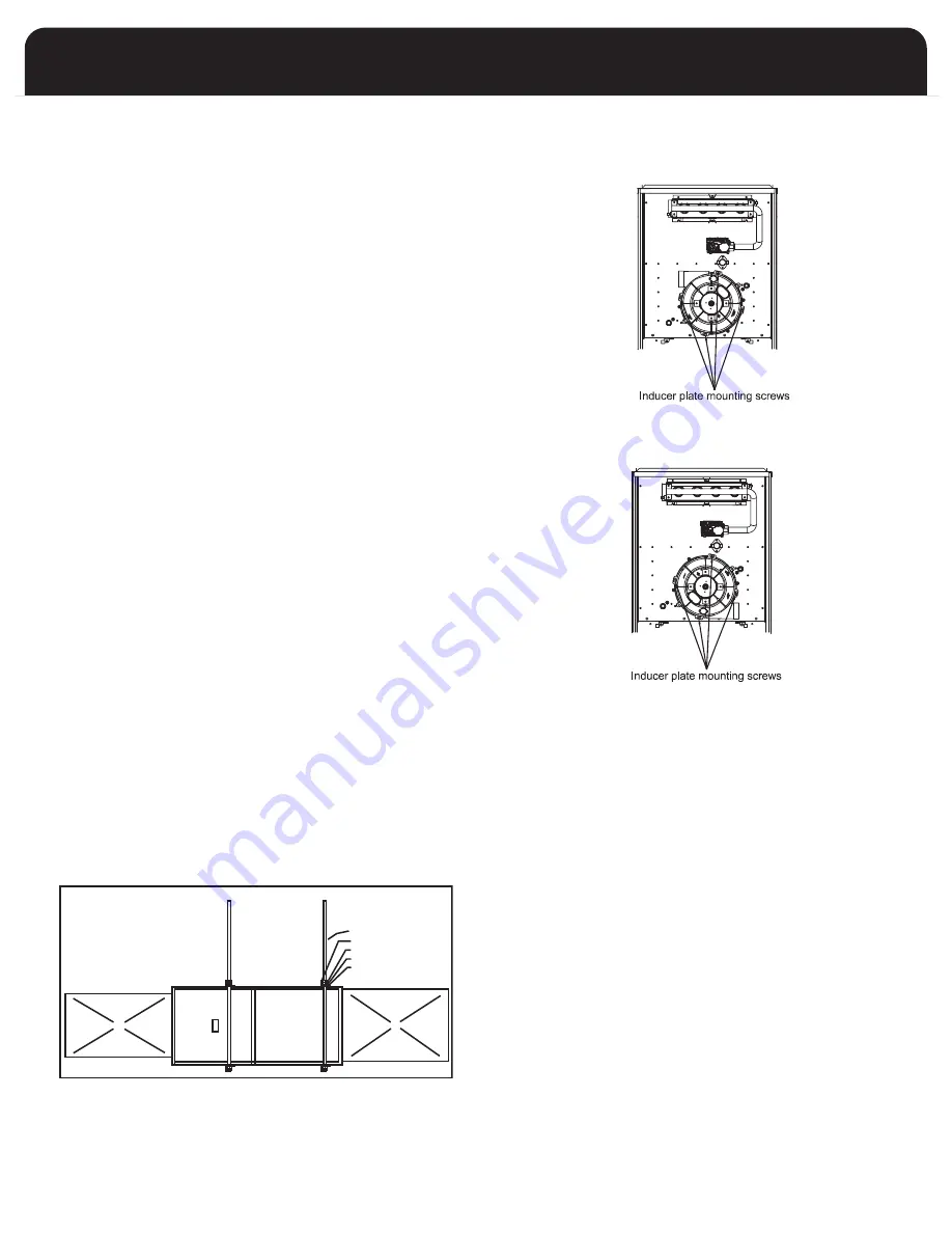
FIGURE A : RIGHT INDUCER POSITION
FIGURE B : LEFT INDUCER POSITION
SUGGESTED METHOD FOR
SUSPENDING HORIZONTAL FURNACE
ALLOW ENOUGH ANGLE
IRON OVERHANG TO
PERMIT OPENING THE
BLOWER DOOR
3/8 INCH THREADED ROD
2 INCH ANGLE IRON
JAM NUTS
LOCK WASHER
FLAT WASHER
SUPPLY AIR PLENUM
RETURN AIR PLENUM
SUSPENDED INSTALLATION
INSTALLATION POSITIONS
Non-Suspended Installation
Maintain clearances to combustibles as outlined in Table 2
on page 6. The furnace must be supported in such a way
as to not allow twisting or sagging of the cabinet.
Horizontal Suspended Installation
or left position by field fabricated a cradle of angle iron and
threaded rod. Secure the furnace with 2 inch minimum
slotted angle or equivalent, as shown in figure below. The
furnace must be supported in such a way as not to allow
twisting or sagging of the cabinet. Position the supports so
as not to interfere with accessing the burner and blower
compartments.
The furnace may be suspended in either the horizontal right
9
Summary of Contents for FV95A054
Page 42: ......


