F6
3.
3-min. compressor switch on delay
The compressor is not switched on again immediately after being switched off. The
air-con controller waits for 3 minutes before turning it on again to protect it.
This protective measure applies throughout the operation of the air-con except on
power-up.
4.
60-second 4-way valve delay
(applicable on Heat Pump Unit only)
This refers to the 60-second delay after turning off
compressor before the 4-way valve is switched over from off to on or vice-versa.
This delay allows the safe, gradual transition of the air-con operation from a cooling
function to heating function or vice versa.
5.
Cool fan prevention in heat mode
(applicable on Heat Pump Unit only)
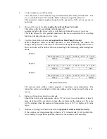
When compressor starts in heating operation or after defrosting, the indoor fan
changes the speed due to the indoor coil thermistor temperature and operation time to
blow out warm air.The indoor fan runs according to the following table during heat
mode:
STEP 1:
ID Coil Temp., T T<=28
°
C
28
°
C<T<30
°
C
T>=30
°
C
ID Fan
STOP
*
LOW
STEP 2:
ID Coil Temp., T T<=33
°
C
33
°
C<T<36
°
C
T>=36
°
C
ID Fan
LOW
*
SET
STEP 3:
ID Coil Temp., T T<=46
°
C
46
°
C<T<50
°
C
T>=50
°
C
ID Fan
SET
*
HIGH
* Maintain current state
The start-up warm airflow control program is regardless room temperature. The
indoor fan is also not switched on while the outdoor coil is being de-iced for the same
reason.
6.
Indoor coil icing prevention in cool mode
Should the indoor coil temperature dip to 2°C or lower in cool mode for at least 2
mins, de-icing will be executed to remove the ice formed at the indoor coil. De-icing
will be stopped when the indoor coil temperature rises to 10°C or higher or 10 mins
lapse.
7.
Outdoor coil icing prevention in heat mode
(applicable on Heat Pump Unit only)
If the outdoor coil temperature dips to below -4°C in heat mode. It will perform De-
ice according to a specified algorithm, and de-ice the outdoor coil if necessary.
Summary of Contents for E1FC418N6G
Page 1: ...ISSUED ON 1 APRIL 2003 FEDDERS LARGE SPLIT UNIT R407C SERVICE MANUAL ...
Page 3: ...SECTION A SPECIFICATIONS ...
Page 5: ...SECTION B PARTS LIST AND EXPLODED VIEWS ...
Page 10: ......
Page 11: ......
Page 12: ......
Page 16: ......
Page 17: ......
Page 18: ......
Page 19: ......
Page 20: ...SECTION C INSTALLATION ...
Page 21: ...SPLIT TYPE AIR CONDITIONER INSTALLATION MANUAL For 18 000 24 000 Btu C1 ...
Page 39: ...SECTION D TROUBLE SHOOTING ...
Page 40: ...D1 ...
Page 42: ...SECTION E WIRING DIAGRAM ...
Page 43: ...E1 ...
Page 44: ...E2 ...
Page 45: ...E3 ...
Page 46: ...E4 ...
Page 47: ...SECTION F TECHNICAL DATA ...
Page 68: ...F21 ...
Page 69: ...F22 ...
Page 70: ...F23 ...
Page 71: ...F24 ...
Page 72: ...F25 ...
Page 73: ...F26 ...
Page 74: ...F27 ...
Page 75: ...F28 ...


