19
MAINTENANCE MANUAL MODELS 825Y, 825YA, 825, 825D, 825YD & 826YD
d.
Un-thread capscrew (Item 7A) using
9
/
16
" hex socket.
e.
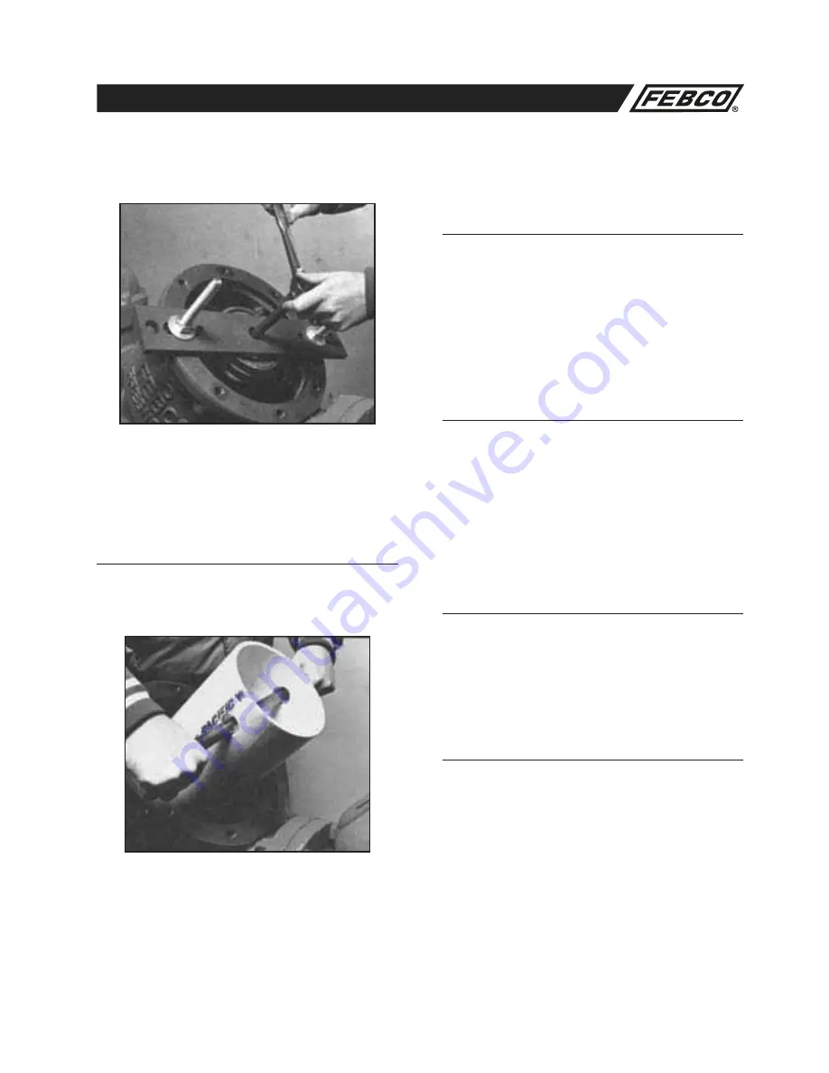
Release spring tension by un-threading nuts on long studs.
Use alternating turns to keep tool parallel to valve body.
f.
Remove spring guide and stem assembly.
g.
Remove guide bushing by un-threading.
4a. Valve Seat Removal (Sizes 4–10")
Threaded-in Seat Ring Type Model 825
(See Figure No. 13)
1.
Remove check valve as described above.
2.
Remove seat ring by un-threading in the counterclockwise
direction. For ease of removal, Figure No. 21 on page 30
defines a simple tool for this purpose.
3.
Remove bushing and bushing nut if used (bushing and nut
is used on older Model 825).
4. Remove o-ring.
4b. Valve Seat Removal (Sizes 4–10") Bolted
in Seat Ring Type Model 825D and 825YD
(See Figure No. 14)
1.
Remove check valve as described above.
2.
Remove the three capscrews and washers
retaining the seat ring.
3.
Pull the seat ring from the valve body.
4.
Un-thread the bushing (Item 2A) from the
seat ring.
5.
Remove the o-ring.
5a. Valve Seat Reassembly (Sizes 4–10")
Threaded-in Seat Ring Type Models
Model 825 (See Figure No. 13)
1.
Lubricate o-ring with FDA approved lubricant. Reposition the
o-ring in the seat ring groove.
2.
Replace the bushing and bushing nut (if used) in the seat
ring (the bushing and nut is used on older Model 825).
3.
Thread the seat ring into the seating area in a clockwise
direction. Be careful not to damage internal epoxy coated
surfaces.
5b. Valve Seat Reassembly (Sizes 4–10")
Bolted-in Seat Ring Type Models
Model 825D and 825YD
(See Figure No. 14)
1.
Lubricate o-ring with FDA approved lubricant. Reposition the
o-ring in the seat ring groove.
2.
Thread the bushing into the seat ring.
3.
Place the seat ring carefully into the valve body and retain
with three capscrews and washers being careful not to
damage the internal expoxy coated surfaces.
6. Check Valve Reassembly
Models 825, 825D and 825YD
a.
Use reverse procedure for assembly.
b.
Make sure the o-ring is properly placed in the groove. Do
not force the cover into the body.
c.
Do not damage epoxy coated surfaces.
d.
Test unit to ensure proper operation.
Service Procedures 825, 825D and 825YD (4–10") (Continued)


