16
MAINTENANCE MANUAL MODELS 825Y, 825YA, 825, 825D, 825YD & 826YD
Service Procedures 825, 825D, 825YD and 826YD
(2
1
/
2
–3")
3a. Valve Seat Removal (Sizes 2½
–3")
Threaded-in Seat Ring Type Models
Model 825 (See Figure No. 13)
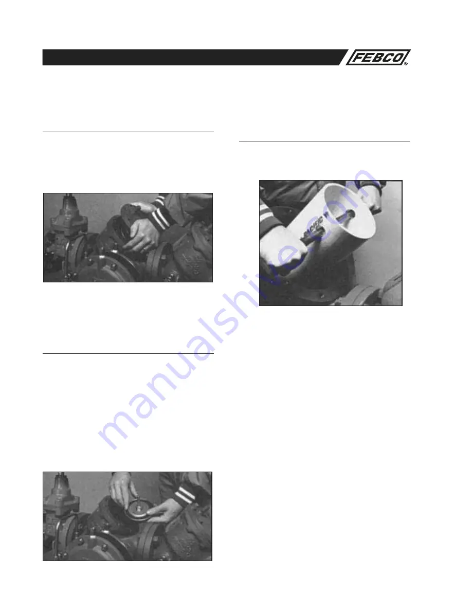
1.
Remove seat ring by un-threading in counterclockwise
direction being careful not to damage the internal epoxy
coating in valve. A tool to aid in this process is described in
Figure No. 21 on page 30.
2.
Remove bushing and bushing nut (item 2A & 2B).
3.
Remove o-ring.
1. Check Valve Disassembly Models 825, 825D
and 825YD (Sizes 2
1
/
2
–3") (See Figure No. 13)
a.
Slowly close outlet shutoff valve and inlet shutoff valve.
Bleed residual pressure by opening #4, #3 and # 2 test
cocks. See Figure No. 8 for test cock location.
b.
Remove cover bolts uniformly while holding cover in place.
Remove cover.
CAUTION: Spring is retained in body by cover.
c.
Lift check assembly from body being careful not to damage
internal epoxy coating.
d.
If necessary, un-thread bushing (item 4A) from cover.
2. Check Assembly Repair Models 825 825D
and 825YD (Sizes 2
1
/
2
–3") (See Figures
No. 15 & 16)
a.
Un-thread nut on stem and remove disc washer and seat
disc.
b.
Inspect seat disc for wear or damage. Replace with new
seat disc or turn used disc over if new disc is not available.
NOTE: The discs are symmetrical. It is usually possible to turn
the disc over and obtain an effective seal.
c.
If the seat disc has been severely cut along the seat disc
ring diameter, the assembly is being subjected to extremely
high back pressure from thermal water expansion, water
hammer, or other causes of excessive water pressure. A
disc damaged in such a manner should be replaced and not
turned over to be reused.


