background image

3.2

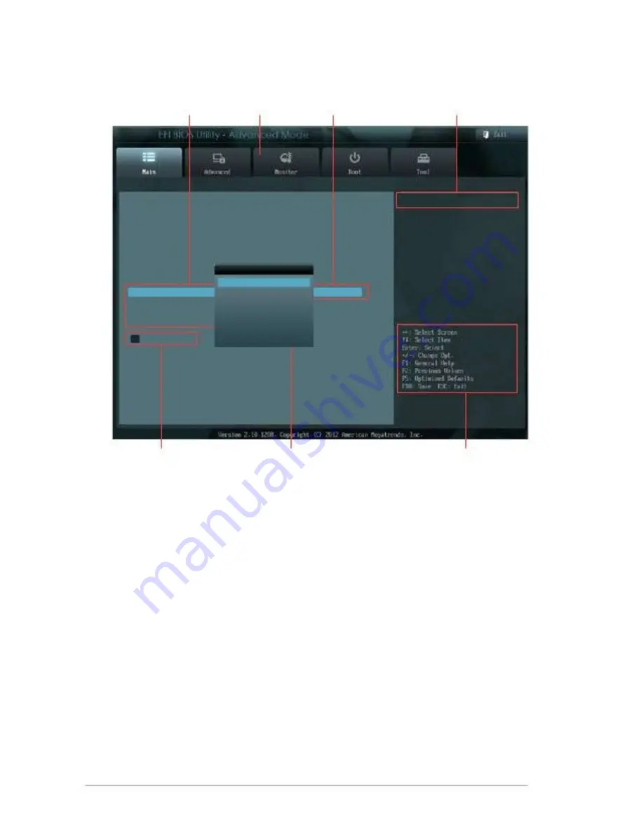
BIOS menu screen

Menu items

Menu bar

Configuration fields

General help

BIOS Information
BIOS Version
Build Date

CPU Information
Intel(R) Atom(TM) CPU 600 @ 1.60GHz
Speed

Memory Information
Total Memory

System Language

System Date
System Time

Access Level

> Security

System Language

English
Français
Español
Deutsch

Русский

0202 x64

11/30/2012

Choose the system default language

1600 MHz

2048 MB

English

[Saturday 01/03/2009]
[16:46:15]

Administrator

Submenu items

Pop-up window

Navigation keys

Menu bar

The menu bar on top of the screen has the following main items:

Main

Advanced

Monitor

Boot

Tool

Exit

For changing the basic system configuration.

For changing the advanced system settings.

For displaying the system temperature, power status, and
changing the fan settings

For changing the system boot configuration.

For configuring options for special functions.

For selecting the exit options and loading default settings.

3-2

faytech Motherboard

Summary of Contents for Industrial Motherboard Series

Page 1: ...faytech Industrial Motherboard Series Industrial Motherboard ...

Page 2: ...ithout notice While reasonable efforts have been made in the preparation of this document to assure its accuracy the original manufacturer assumes no liabilities resulting from errors or omissions in this document or from the use of the information contained herein faytech reserves the right to make changes in the product design without notice to its users Acknowledgments All other products name o...

Page 3: ... 8 Connectors 2 12 2 7 1 2 7 2 Rear panel connectors 2 12 Internal connectors 2 13 Chapter 3 3 1 3 2 3 3 BIOS setup program 3 1 BIOS menu screen 3 2 Main menu 3 4 3 3 1 3 3 2 3 3 3 3 3 4 System Language English 3 4 System Date Day xx xx xxxx 3 4 System Time xx xx xx 3 4 Security 3 4 Contents Chapter 1 1 1 1 2 Package contents 1 1 Specifications 1 2 Before you proceed 2 1 Motherboard layout 2 2 Scr...

Page 4: ...3 9 Chassis Fan Speed xxxx RPM or N A 3 9 Chassis Q Fan Control Enabled 3 10 CPU Voltage 3 3V Voltage 5V Voltage 12V Voltage 3 10 Bootup NumLock State On 3 10 Full Screen Logo Disabled 3 11 Wait for F1 If Error Enabled 3 11 Boot Option Priorities 3 11 Boot Override 3 11 Boot menu 3 10 Tools menu 3 11 Exit menu 3 12 Appendix Notices A 1 iv ...

Page 5: ...ng items 1 2 Features Integrated Intel Atom processor N2600 N2800 optional Realtek ALC887 Audio Amplifier EUA 2012A Dual Ethernet LAN Realtek 8111F x 2 SATA 3Gb s x 2 USB2 0 x 6 COM x 4 One Single Channel DDR3 800 1066MHz SO DIMM Up To 2GB Multi Display LVDS HDMI VGA LVDS VGA HDMI 2 x Mini Card slots with PCIe and USB interface 1 x Full Height with SIM card interface 1 x Half Height 1 x PCIe 1 x s...

Page 6: ... Inverter Control Battery Power requirement Power compliance Operating temperature Operating humidity Form factor EMI 64Mb Flash ROM UEFI AMI BIOS PnP DMI 2 0 Wfm 2 0 SM BIOS ACPI 3 06 Monitors CPU system temperature Monitors chassis fan speed Yes Yes WOL PXE S3 S4 S5 Monitors Vcore 3 3V 5V 12V voltages 1 255 steps by software program AMD HD7410M with 512M memory optional LVDS HDMI VGA LVDS VGA HD...

Page 7: ...ck panel I O ports 1 x HDMI port I O Placement 1 x COM port RS232 485 2 x LAN RJ 45 port 4 x USB 2 0 ports Internal I O connectors 1 x Lockable DC power port 12V 1 x VGA pin header 1 x 12V DC power connector 2 pin 2 x SATA 3Gb s connectors 1 x 4 pin SATA power connector 1 x PS 2 keyboard mouse connector 6 pin 3 x RS232 COM connectors 1 x LVDS connector 1 x USB 2 0 header supports additional 2 USB ...

Page 8: ...Windows XP 64 bit only with AMD graphics Windows 7 64 bit only with AMD graphics Windows 8 64 bit only with AMD graphics Accessories 1 x SATA 3Gb s cable 1 x SATA power cable 1 x Support DVD Drivers Manual NOTE Specifications are subject to change without notice 1 4 faytech Motherboard ...

Page 9: ... or a metal object such as the power supply case to avoid damaging them due to static electricity Hold components by the edges to avoid touching the ICs on them Whenever you uninstall any component place it on a grounded antistatic pad or in the bag that came with the component Before you install or remove any component ensure that the power supply is switched off or the power cord is detached fro...

Page 10: ...vertighten the screws Doing so can damage the motherboard 1 2 PCIeX1 3 11 5cm 4 53in AAFP1 4 5 AMP_CON1 SPEAKER SPDIF_OUT1 HDMI1 ALC 887 MINI_CARD1 SPI1 SIM1 ICS 9VRS4339AL SATA3G_2 SATA3G_1 ISD72 D9MGG 6 7 AMD HD7410M LAN1 RTL 8111F AMD GPU optional PEX8605 ISD72 D9MGG MINI_CARD2 PLX LAN2 USB2 RTL 8111F Intel NM10 R560 010S LVDS1 16 5cm 6 5i n DIO1 COM2 COM1J2 N2600 BATTERY LVDS_VDD_SEL1CLRTC 1 2...

Page 11: ...9 pin COM2 3 4 15 Chassis fan connector 4 pin CHA_FAN1 16 Clear RTC RAM 3 pin CLRTC1 17 LVDS panel VDD setting jumper 3 pin LVDS_VDD_SEL1 18 PCIeX1 Straddle 19 EATX power connector 2 pin EATX_PWR1 12V DC IN 1 2 GND 20 Lockable DC power port DC_PWR 12V DC IN 21 SATA power connector 4 pin SATA_PWR1 22 COM1 Ring and voltage selection 6 pin J1 23 Battery connector 2 pin BATTERY 24 AT Mode selection 2 ...

Page 12: ...2 3 2 3 1 Screw size Component side 2 4 faytech Motherboard ...

Page 13: ...2 3 2 Solder side Chapter 2 Motherboard information 2 5 ...

Page 14: ...ocessor 2 5 System memory This motherboard comes with one Double Data Rate 3 DDR3 Small Outline Dual Inline Memory Modules SO DIMM socket The figure illustrates the location of the DDR3 DIMM socket DIMM_A1 faytech Industrial Motherboard Series DDR3 DIMM socket faytech Industrial Motherboard Series PCIxe1 Straddle 3 2 6 faytech Motherboard faytech Industrial Motherboard Series Integrated Intel Atom...

Page 15: ...To install a DIMM To remove a DIMM 3 Chapter 2 Motherboard information 2 7 ...

Page 16: ...or about 5 10 seconds then move the cap back to pins 1 2 Plug the power cord and turn ON the computer Hold down the Del key during the boot process and enter BIOS setup to reenter data CAUTION Except when clearing the RTC RAM never remove the cap on CLRTC jumper default position Removing the cap will cause system boot failure NOTES If the steps above do not help remove the onboard battery and move...

Page 17: ... Default faytech Industrial Motherboard Series COM1 Ring and voltage selection Pins 1 2 3 4 5 6 12V 5V Ring Default 3 AT Mode selection 2 pin J2 J2 PIN1 AT MODE faytech Industrial Motherboard Series AT Mode selection Pins 1 2 AT Mode Chapter 2 Motherboard information 2 9 ...

Page 18: ...Industrial Motherboard Series LVDS backlight brightness control jumper Pins 1 2 2 3 DC Mode Default PWM Mode 5 LVDS panel VDD setting jumper 3 pin LVDS_VDD_SEL1 LVDS_VDD_SEL1 2 1 2 3V 5V Default faytech Industrial Motherboard Series LVDS panel VDD setting jumper Pins 1 2 2 3 3V 5V Default 3 2 10 faytech Motherboard ...

Page 19: ...ower setting jumper 3 pin LCD_POWER_SEL1 LCD_POWER_SEL1 2 1 2 12V Default 5V faytech Industrial Motherboard Series LCD inverter power setting jumper Pins 1 2 2 3 12V Default 5V Chapter 2 Motherboard information 3 2 11 ...

Page 20: ...N1 Gbps connection Activity Link LED Speed LED HDMI port This port is for a High Definition Multimedia Interface HDMI connector and is HDCP compliant allowing playback of HD DVD Blu Ray and other protected content LAN port 3 4 5 COM port This 9 pin COM1 port is for pointing devices or other serial devices USB 2 0 ports These two 12 pin Universal Serial Bus USB ports are available for connecting US...

Page 21: ...ctor 4 1 pin SPDIF_OUT1 This connector is for an additional Sony Philips Digital Interface S PDIF port Connect the S PDIF Out module cable to this connector then install the module to a slot opening at the back of the system chassis PIN 1 SPDIF_OUT1 faytech Industrial Motherboard Series Digital audio connector NOTE The S PDIF module is purchased separately Chapter 2 Motherboard information A_SPDIF...

Page 22: ...ial port connectors WtoB CON 9P 1 25mm S T SMT ACES 50273 00971 001 9 pin COM2 3 4 These connectors are for serial COM ports Connect the serial port module cable to this connector then install the module to a slot opening at the back of the system chassis COM4 GND RI DTR CTS TXD RTS RXD DSR DCD PIN 1 COM3 GND RI DTR CTS TXD RTS RXD DSR DCD PIN 1 COM2 GND RI DTR CTS TXD RTS RXD DSR DCD PIN 1 faytec...

Page 23: ... connect the fan cable to the fan connector Insufficient air flow inside the system may damage the motherboard components This is not a jumper Do not place jumper caps on the fan connector 6 The 4 pin connector is for the chassis mounted system warning speaker The speaker allows you to hear system beeps and warnings SPEAKER PIN 1 Internal speaker connector 4 pin SPEAKER 5V GND GND SPKO faytech Ind...

Page 24: ...hen the system is in sleep mode Hard disk drive activity LED 2 pin HD_LED This 2 pin connector is for the HDD Activity LED Connect the HDD Activity LED cable to this connector The IDE LED lights up or flashes when data is read from or written to the HDD ATX power button soft off button 2 pin PWR BTN This 2 pin connector is for the system power button Reset button 2 pin RESET System power LED 2 pin...

Page 25: ...using Serial ATA hard disk drives When using hot plug and NCQ set the Configure SATA as item in the BIOS to AHCI See section 3 4 2 IDE Configuration for details 9 This connector is for the SATA power cable The power cable plug is Designed to fit this connector inonly one orientation Find the proper Orientation and push down firmly until the connector completely fit SATA power connector 4 pin SATA_...

Page 26: ...USB1 PIN 1 5V USB4 _R USB4 _R GND GND GND GND USB5 _R USB5 _R 5V faytech Industrial Motherboard Series USB 2 0 connector CAUTION Never connect a 1394 cable to the USB connector Doing so will damage the motherboard NOTE The USB module cable is purchased separately 11 Use this connector to flash BIOS SPI ROM GNDSPI_CLKSPI_MO SI NC SPI programming connector 8 pin SPI1 SPI1 V3 3SPISPI_CS SPI_ MISO NC ...

Page 27: ...oard mouse connector 13 Backlight inverter power connector WAFER HD 5P S T 2 0mm WHITE PINREX 721 81 05TW00 5 pin INV1 Connect the backlight inverter power cable to this connector INV1 VCC_LVDS1_BKLT L_BRIGHTNESS1 GND GND BKLT_EN faytech Industrial Motherboard Series Backlight inverter power connector NOTE The backlight inverter power cable is purchased separately Chapter 2 Motherboard information...

Page 28: ...C GND NC GND GND 5V GND NC RDDCA_DATA_R R_HSYNC R_VSYNC RDDCA_CLK_R GND faytech Industrial Motherboard Series VGA connector 15 Audio amplifier connector WtoB CON4P 1 25mm S T SMT ACES A 85025 04701 4 pin AMP_CON1 This connector is for an external audio amplifier AMP_CON1 LOUTPLOUTNROUTNROU TP PIN 1 faytech Industrial Motherboard Series Speaker out connector 2 20 faytech Motherboard ...

Page 29: ...DP2 LDDC_DATA LVDS_DN3 LVDS_DP3 VDD_LVDS1 LVDS_CLKN L_BRIGHTNESS1 LVDSB_L0N_GPU LVDSB_L0P_GPU GND LVDSB_L1N_GPU LVDSB_L1P_GPU GND LVDSB_L2N_GPU LVDSB_L2P_GPU LDDC_CLK LVDSB_L3N_GPU LVDSB_L3P_GPU GND LVDSB_LCLKN_GPU faytech Industrial Motherboard Series LVDS connector 17 Battery connector 2 pin BATTERY This connector is for the lithium CMOS battery BATTERY GND BATT1 PIN 1 faytech Industrial Motherb...

Page 30: ...upport various devices DIO1 PIN 1 DIO_P 1 GPIO80 DIO_P 3 GPIO82 DIO_P 5 GPIO84 DIO_P 7 GPIO86 5V DIO_P 2 GPIO81 DIO_P 4 GPIO83 DIO_P 6 GPIO85 DIO_P 8 GPIO87 GND faytech Industrial Motherboard Series Digital I O connector NOTE To configure the I O pins in BIOS go to the Advanced tab DIO Function GPIO 1 8 See section 3 4 6 DIO Function for details 2 22 faytech Motherboard ...

Page 31: ...a running operating system can cause damage to your data or system We recommend to always shut down the system properly from the operating system IMPORTANT The default BIOS settings for this motherboard apply for most conditions to ensure optimum performance If the system becomes unstable after changing any BIOS settings load the default settings to ensure system compatibility and stability Select...

Page 32: ...language 1600 MHz 2048 MB English Saturday 01 03 2009 16 46 15 Administrator Submenu items Pop up window Navigation keys Menu bar The menu bar on top of the screen has the following main items Main Advanced Monitor Boot Tool Exit For changing the basic system configuration For changing the advanced system settings For displaying the system temperature power status and changing the fan settings For...

Page 33: ...er Pop up window Select a menu item and press Enter to display a pop up window with the Configuration options for that item Navigation keys At the bottom right corner of the menu screen are the navigation keys for the BIOS setup program Use the navigation keys to select items in the menu and change the settings General help At the top right corner of the menu screen is a brief description of the s...

Page 34: ...6 15 Administrator 3 3 1 Allows you to choose the BIOS language version from the options Configuration options English Français Español Deutsch Русский System Language English 3 3 2 3 3 3 3 3 4 Allows you to set the system date Allows you to set the system time System Date Day xx xx xxxx System Time xx xx xx Security The Security menu items allow you to change the system security settings NOTES If...

Page 35: ...te confirm the password After you clear the password the Administrator Password item on top of the screen shows Not Installed User Password If you have set a user password you must enter the user password for accessing the system The User Password item on top of the screen shows the default Not Installed After you set a password this item shows Installed To set a user password 1 2 Select the User ...

Page 36: ...ms in this menu show the CPU related information that the BIOS automatically detects Hyper threading Enabled The Intel Hyper Threading Technology allows a hyper threading processor to appear as two logical processors to the operating system allowing the operating system to schedule two threads or processes simultaneously Enabled Disabled Enabled Two threads per activated core are enabled Only one ...

Page 37: ...eases storage performance on random workloads by allowing the drive to internally optimize the order of commands 3 4 3 The items in this menu allow you to change the USB related features NOTE The USB Devices item shows the auto detected values If no USB device is detected the item shows None USB Configuration EHCI Hand off Disabled Enabled Disabled Enables the support for operating systems without...

Page 38: ... configurethe resolution for the LVDS panel Configuration options 800x600 18bit 800x480 18bit 1024x768 24bit 1280x800 18bit 1280x1024 48bit 1440x900 48bit 1680x1050 48bit 1920x1080 48bit EDID Panel Option Enabled Enables or disables the EDID panel Configuration options Enabled Disabled 3 4 8 Onboard Devices Configuration Onboard WLAN Enabled Enabled Disabled Enabled Enables the onboard wireless LA...

Page 39: ...llows you to change the fan settings 3 5 1 The onboard hardware monitor automatically detects and displays the CPU and motherboard temperatures Select Ignore if you do not wish to display the detected temperatures CPU Temperature MB Temperature xxxºC xxxºF 3 5 2 The onboard hardware monitor automatically detects and displays the chassis fan speed in rotations per minute RPM If the fan is not conne...

Page 40: ...nding on the chassis temperature Sets to Silent to minimize the fan speed for quiet chassis fan operation Sets to Turbo to achieve maximum chassis fan speed 3 5 4 The onboard hardware monitor automatically detects the voltage output through the onboard voltage regulators Select Ignore if you do not want to detect this item CPU Voltage 3 3V Voltage 5V Voltage 12V Voltage 3 6 Boot menu The Boot menu...

Page 41: ...S To selectthe boot device during system startup press F8 after the first screen appears To access Windows OS in Safe Mode press F8 after POST Wait for F1 If Error Enabled Boot Option Priorities 3 6 5 These items displays the available devices The number of device items that appears on the screen depends on the number of devices installed in the system Click an item to start booting from the selec...

Page 42: ...onfirmation window appears Select Yes to load the default values Save Changes Reset Once you are finished making your selections choose this option from the Exit menu to ensure the values you selected are saved When you select this option or If you press F10 a confirmation window appears Select Yes to save changes and exit Discard Changes Exit This option allows you to exit the Setup program witho...

Page 43: ...rient or relocate the receiving antenna Increase the separation between the equipment and receiver This device must accept any interference received including interference that may cause undesired operation Connect the equipment to an outlet on a circuit different from that to which the receiver is connected Consult the dealer or an experienced radio TV technician for help WARNING The use of shiel...

Page 44: ... A Warehouse 121 Varick Street 3rd Floor New York NY 10013 RMA service If you think your faytech product has a defect please always contact us directly Our trained after sales service specialists can help you resolve your problems Please check the manual and our frequently asked questions before contacting us you will usually find an answer to your question If there is a defect you can request an ...

Reviews: