Maintenance every year
BOMAG
46
BT 60/4, BT 65/4
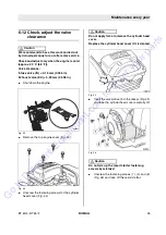
Fig. 47
l
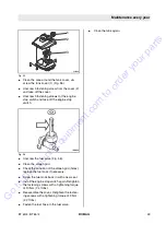
Align the alignment mark on the flywheel rib
(Fig. 47) with the top bore in the fan cover .
Note
i
The piston is in top dead centre of the compres-
sion stroke.
However, if the exhaust valve is open when align-
ing the marks, the flywheel must be turned further
by 360°.
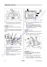
Fig. 48
l
Measure the valve clearance with a feeler
gauge (2) (Fig. 48).
l
To adjust the valve hold the valve adjustment
screw (1) and loosen locking nut (3).
l
Turn the valve adjustment screw in or out, as
required.
l
Retighten the locking nut with a tightening
torque of 7.5 Nm (5.5 ft.lbs).
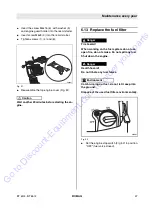
Fig. 49
l
Clean the sealing faces on cylinder head cover
and cylinder block.
l
Apply a bead of liquid gasket (Three Bond
1207B or similar) with a diameter of approx.
1.5 to 2 mm (0.06 to 0.08 in) to the inside of the
cylinder head cover (Fig. 49).
Note
i
Attach the cylinder head cover within the next 10
minutes.
l
Place the cylinder head cover on the cylinder
block and tighten the fastening screws.
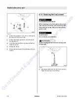
Fig. 50
Caution
!
Do not mix up the recoil starter fastening
screws by mistake!
Mount the recoil starter to the engine housing:
l
Insert the screw M6x12 (1) (Fig. 50) with
washer (2) and clamp (3) into the recoil starter.
Go
to
Discount-Equipment.com
to
order
your
parts

