background image

Manual No. SCAZ043075 1.7.01

35

E&OE

M25H Road Sweeper

Operating Instructions

Using the auxiliary hand pump

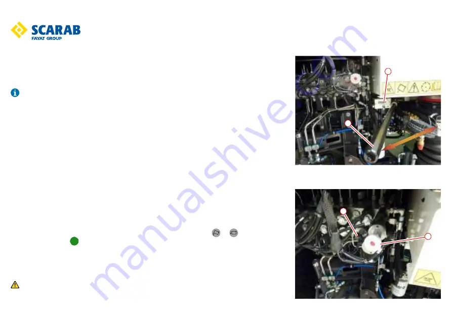
In the event of hydraulic system failure, an auxiliary manually operated hydraulic pump is fitted, to 

enable the hopper to be operated. This is located on the left hand side of the vehicle, adjacent to the 

hydraulic and water valves. The pump handle is stowed in the cab in a locker under seat.

It should be noted that it will require a substantial number of pumping cycles to complete the 

following operations. The assistance of a second person is preferable.

Follow the procedure below:

1. Switch the engine and ignition off. Apply the handbrake.

2. Open left hand gantry door to access the main valve block.

3. Insert the pump handle

 q

, into the pump 

w

.

4. To raise hopper, press in and turn to latch the control on top of raise and lower solenoid 

e

.

To lower hopper, pull out and turn to latch the control on top of raise and lower solenoid 

e

.

5. Push in and hold unloader valve 

r

.

6. Operate the pump handle to raise or lower the hopper manually.

7. When hopper is in position required, release unloader valve 

r

 and unlatch control 

e

.

8. Stow handle when finished with.

Alternate procedure, this will require two people to perform:

1. Apply the handbrake. Switch the ignition on but do not start engine.

2. Insert the pump handle

 q

, into the pump 

w

.

3. One person is required to press and hold the raise or lower buttons   or   and the safety 

interlock button   on the remote control.

4. Second person then operates the pump handle to raise or lower the hopper manually.

5. When hopper is in position required, release the buttons on the remote control.

6. Stow pump handle when finished with.

Never work under a raised hopper unless an appropriate prop is used.

4

3

2

1

Summary of Contents for SCARAB M25H

Page 1: ...M25H Road Sweeper Operating and Basic Maintenance Instructions This document contains important Health and Safety Advice and must remain with the vehicle at all times ...

Page 2: ...igh pressure retractable hose option 15 Wander hose standard 16 Fuel filler 17 Rear view camera 18 Warning beacon 1 Air filter and low pressure water pump cover 2 Low pressure water filter 3 Front brush assembly 4 Wide sweep assembly 5 Side loading hatch 6 High pressure water pump under hopper 7 High pressure water filter 8 Front spray bar s 9 Auxiliary hand pump 15 15 1 2 3 3 4 5 5 6 7 8 8 10 11 ...

Page 3: ...rt is made to ensure that the information it contains is correct at the time of publication Due to a policy of continuous development however the Company reserves the right to alter the specification and to supply when so altered without reference to illustrations and descriptions in this manual Scarab Sweepers Limited Pattenden Lane Marden Tonbridge Kent TN12 9QD United Kingdom T 44 0 1622 831 00...

Page 4: ...raulic Tank 42 litres Water Tank 450 litres Brake System 0 7 litres Air conditioning gas Type R134a 800grams High Pressure Water Pump 0 55 litres Tyre Size 225 65R 16C Front Tyre Pressure 62PSI 4 27bar Rear Tyre Pressure 79PSI 5 44bar Wheel Nut Torque 170 Nm Noise levels In cab Between 70 84 dB A dependent on operating speed External Maximum LWA of 104 dB A in accordance with directive 2000 14 EC ...

Page 5: ...ter A boosted start will burn out the vehicle electronic control nodes If the batteries on the vehicle are not charged then always use a fresh set of batteries WARNING Electrical Interference CB Radios and other electrical equipment used within the sweeper should be properly suppressed EMC to prevent the possibility of interference to the sweeper electronic systems WARNING DEUTZ TCD 2 9L4 engine f...

Page 6: ...en transporting the vehicle it shall be secured to the transporter by means of suitable straps as follows Front Wheels One strap per wheel using wheel loops to a forward and rearward lashing point Rear Wheels One strap per wheel using wheel loops to a forward and rearward lashing point Front One strap each end of front bumper to a forward lashing point ...

Page 7: ...ocated in the cab on the panel just beneath the front of the seats The Scarab M25H has a four digit serial number The CHASSIS NUMBER is stamped on the top face of the right hand chassis rail beneath the cab Not all components and options shown in this manual may be available on your vehicle Showing new style VIN plate and Serial Number plate ...

Page 8: ... water can be hazardous Always wear suitable face protection when operating the high pressure water pump and when using the lance Do no direct the water jet at other persons Beware of electrical installations on public buildings and lamp posts etc Always exercise extreme caution in public places The driver s seat should always be correctly adjusted as to give a good posture when driving Do not adj...

Page 9: ... sharp objects e g broken glass discarded hypodermic syringes while operating or working on the vehicle Exposure to various infectious diseases e g Legionnaire s Weil s Hepatitis Tetanus while operating or working on the vehicle Safety precautions When using external equipment such as the high pressure water lance or when dealing with potentially hazardous situations while sweeping e g unblocking ...

Page 10: ...inside the hopper If swept dry more of the finer material will pass through the screen wearing out the fan blades on its way back to the environment behind you Operator training Operators should be trained in the following elements Health and safety observations notices Transit driving In cab and external controls Hopper and cab safety prop use Brush setting Nozzle flap adjustment Correct sweeping...

Page 11: ...ls 4 Vibration 4 DEUTZ Auxiliary Engine 5 Warnings 5 Transporting 6 Identification plates 7 Health and Safety advice 8 Hazard awareness 9 Safety precautions 9 Operating advice 10 Operator training 10 Table of Contents 11 Cab area 17 Opening the door external 17 Opening the door internal 17 Opening closing the windows 17 Entering leaving the vehicle 18 Mirrors 18 Interior light 18 Seat adjustment 1...

Page 12: ...and mirror switches 22 Steering column mounted controls 23 Turn signal control 23 Windscreen wiper control 23 Main beam control 23 Drive control 23 Horn 23 Standard rear camera viewing screen 24 Cab fuse and relay panel LHD 25 Fuse Relay Function Amp 25 X3 3 Body builder plug 25 Cab fuse and relay panel RHD 26 Fuse Relay Function 26 X3 3 Body builder plug 26 The CAN bus system 27 Overview 27 Switc...

Page 13: ...ard rear door 34 Using the auxiliary hand pump 35 Hopper safety prop 36 Deploying hopper safety prop 36 Retracting the hopper safety prop 36 Dust suppression system 37 Low pressure water system 37 Filling the water tank 37 Draining the water system 37 High pressure water system 38 Using the high pressure water system 38 Hand lance 39 Retractable hose 39 Attaching the hand lance 39 Hand lance deter...

Page 14: ...ge in the suction path 43 Recommended operator s routine maintenance 44 Lubrication points 45 Basic maintenance 47 Cleaning the suction fan 47 Hopper filter screen cleaning 48 Suction nozzle flap adjustment 49 Brush adjustments 49 Fluid levels 50 Engine coolant 50 Topping up 50 Hydraulic oil tank 51 Topping up 51 High pressure water pump 51 Topping up 51 Filling the Fuel Tank 52 Engine oil 53 Topp...

Page 15: ...up screen 56 Button function 56 Operators screen 57 Button function 57 Operators menu screen 58 Button function 58 Hours screen 59 Camera screen 59 Operator faults selection screen 60 CAN faults screen Deutz Stage V 61 CAN faults screen NOT Deutz Stage V 61 Node error screen 62 Engine faults screen 62 After treatment Deutz Stage V only 63 EOL Test Regen Deutz Stage V only 63 Screen settings 64 Scr...

Page 16: ...043075 1 7 01 16 E OE Operating Instructions Information screen 66 PDF viewer warning screen 66 Options active screen 67 Button check menu 67 Main control panel button check 68 Auxiliary control panel button check 68 Operator Notes 69 ...

Page 17: ...dle w and pull in the direction shown swinging the door outwards Opening the door internal Check the doors swing path is free from any obstructions before opening Grip lever e and squeeze in direction shown swing door outwards Opening closing the windows Press button r to unlock and slide window s in the open or close directions With both windows in the closed position press button t to lock M25H ...

Page 18: ... light when leaving the vehicle Seat adjustment 1 Forward backwards lever lift use 2 Backrest angle lever lift to use 3 Lumber control rotate anticlockwise 4 Headrest raises and angles The driver s seat must only be adjusted when the vehicle is stationary All adjustments should be made when the seat is occupied and before seat belt is fastened Seat belts The seats are equipped with seat belts use ...

Page 19: ...ectronic sweeper controls 1 Auxiliary control panel page 29 2 Instrument panel page 20 3 Ignition switch page 21 4 Sideandheadlights hazard warning indicators rear fog lights beacons and reverse bleeper silence switches page 21 5 Main control panel page 28 6 12v power supply 7 Multi function switch page 29 8 Cab heater controls page 22 9 Drive lever page 32 10 Horn 11 Radio Bluetooth iPod iPhone M...

Page 20: ...mal operating temperature If the temperature increases above 100 C the orange segment will display and then if the temperature increases to over 110 C the red will display and the water temperature symbol at the base of the segments will change to red Fuel level Normal Low Fuel level will be indicated with up to 8 green segments when full 63 litres and when below 7 litres the bottom segment will t...

Page 21: ...elights and headlight work independent of ignition Centre LED illuminates when on Symbol on switch illuminates when on The relevant symbols illuminates on the instrument panel when side and or headlights are on Hazard warning switch Works independent of ignition When on all directional indicator lights flash simultaneously Symbol illuminates when lights are on and flashes when active Rear fog ligh...

Page 22: ...s not permitted Work on the system may only be carried out by qualified personnel Heated seats and mirror switches Located between the seats on the central console are the switches for the heated seats and heated mirrors Heated seats Only work while the engine is running Theheated seats have sensors in them which will allow the seat to heat if seat temperatures is below 10 C and turns off when the...

Page 23: ...n wiper control q Intermittent w Off e Low Speed r High Speed t Push in button on end of lever and hold to activate the screen wash Release to deactivate Main beam control q Main beam activated when lights are on The main beam indicator of the instrument panel illuminates To turnoffmainbeam move control to position w e Off e Activatesmainbeam whenheld in position regardlessof the lights being on o...

Page 24: ... camera view can also be selected via button q if it has been enabled in the options for use when travelling forward When on the camera view screen pressing the encoder w will toggle the view between the two cameras if fitted The display will show the camera view to the left hand side of the screen and on the right hand side it will show the essential operating information Multiple cameras can be ...

Page 25: ...NGINE RUNNING RELAY K3 NEUTRAL START RELAY K4 AIR CON CUT OUT RELAY K101 DIPPED BEAM K102 MAIN BEAM K103 SIDE LIGHT K104 FRONT BEACON K105 REAR BEACON K106 REVERSE LIGHT K107 FOG LIGHT K108 BRAKE LIGHT K109 FLASHER RELAY K110 WIPER RELAY S26 ENGINE DIAG SWITCH X3 3 BODY BUILDER PLUG X22 ENGINE DIAG PLUG TEST FUSE TESTER X3 3 Body builder plug PIN Description Fuse Max Amp 1 BATT POSITIVE F15 5A 2 I...

Page 26: ...INE RUNNING RELAY K3 NEUTRAL START RELAY K4 AIR CON CUT OUT RELAY K101 DIPPED BEAM K102 MAIN BEAM K103 SIDE LIGHT K104 FRONT BEACON K105 REAR BEACON K106 REVERSE LIGHT K107 FOG LIGHT K108 BRAKE LIGHT K109 FLASHER RELAY K110 WIPER RELAY S26 ENGINE DIAG SWITCH X3 3 BODY BUILDER PLUG X22 ENGINE DIAG PLUG TEST FUSE TESTER X3 3 Body builder plug PIN Description Fuse Max Amp 1 BATT POSITIVE F15 5A 2 IGN...

Page 27: ...ns such as start stop sweep mode Green Sweeping functions Blue Water spray functions Each switch illuminates a function related symbol on the LCD monitor installed equipment only and visible in Sweep Mode Each symbol is greyed out until its switch is activated When a switch is activated the appropriate symbol will be illuminated according to system status as illustrated 12 34 Not selected Pre sele...

Page 28: ... brush Press to activate deactivate Left right side brush Press to activate deactivate Left right suction nozzle Press to raise lower Wide sweep brush Press to activate deactivate Left right work light Press to switch on off Left right side brush nozzle water Press to activate deactivate Wide sweep water Press to activate deactivate Reduce increase engine speed Press and hold down to change the sp...

Page 29: ... ON position the lever can be used to control the front brushes and suction nozzle s These additional positions left right and back will return to the central ON position when released Left Move the lever to the left to swing out or retract left front brush es Right Move the lever to right to swing out or retract fright front brush es Back Move the lever back to momentarily tilt the suction nozzle...

Page 30: ... when the hopper is in the raised position Failure to do so could result in serious injury See page 36 Hopper Lower Press and hold to lower the hopper Ensure that the hopper safety prop is returned to its stowage position before attempting to lower the hopper and no obstructions are present under the hopper Failure to do so could result in damage to the machine and or serious injury See page 36 Re...

Page 31: ... noted that warning symbols only illuminate when a specific condition occurs If any of the following DEUTZ engine faults occur the will flash and the warning buzzer will pulse stop and investigate the cause Low engine coolant air filter blocked water in fuel engine protection lamp amber engine stop lamp red oil pressure and high coolant temperature F1 F1 F2 F2 F3 F3 1267 12 34 Engine Speed Option ...

Page 32: ...mode illuminates on instrument panel engine RPM increases to default If engine RPM remains at idle 950 RPM the engine increase switch can be used to adjust the RPM 1250 RPM is considered the most efficient setting for normal sweeping however it may be necessary to increase RPM in certain circumstances i e full load uphill Although 1250 RPM is considered best for normal sweeping engine RPM may be r...

Page 33: ...braking When reverse is selected in sweep mode all active sweeping equipmentwill stop lift and retract automatically These willreturn to their sweeping position when either neutral or forward are selected again Reverting to normal drive 1 With the vehicle stopped hand brake on and neutral w selected using the yellow control lever See page 23 or 32 2 Turn off all active sweeping equipment See page ...

Page 34: ...uum will hold door closed 5 Reverse vehicle to discharge point 6 Switch suction fan off 7 Raise hopper fully It is essential that the hopper controls are operated from outside the vehicle and not within the cab and the operator has a clear view of the hopper and rear door area Never work under a raised hopper without the hopper prop in the safety position 8 With the load fully discharged lower the...

Page 35: ...r press in and turn to latch the control on top of raise and lower solenoid e To lower hopper pull out and turn to latch the control on top of raise and lower solenoid e 5 Push in and hold unloader valve r 6 Operate the pump handle to raise or lower the hopper manually 7 When hopper is in position required release unloader valve r and unlatch control e 8 Stow handle when finished with Alternate pr...

Page 36: ...rop be deployed if any work under the hopper is going to be carried out The hopper safety prop is located underneath the hopper and is usually located kerbside Deploying hopper safety prop Grab the handle and swing the hopper safety prop down and place into the safety cup Retracting the hopper safety prop Raise hopper fully and then swing up the hopper safety prop back into its stowage position un...

Page 37: ...ean water to the top of the level indicated by the side of the sight tube w 4 When full remove hose and close locker door Draining the water system It is vital that the water system is drained totally if the air temperature is expected to fall to 0 c or below 1 Remove the strainer from the inside of the low pressure water filter e which is located under the rear right of hopper They can be opened ...

Page 38: ...an result in serious injury Using the high pressure water system The high pressure water system is a set of optional components High pressure water is used on the follow options Front high pressure spray bar Hand lance To operate any of the above functions 1 Sweep mode must be on 2 Press the high pressure water switch on the auxiliary control panel 3 If using the front high pressure spray bar then...

Page 39: ...ion 4 Attach the lance q to the coupler w 5 Close the front high pressure spray bar shut off valve r 6 The high pressure lance is now ready to use Hand lance detergent Detergent to be used with the high pressure hand lance is an option 1 With the hand lance connected and in use 2 Check detergent container has sufficient fluid 3 Turn the control valve t on 4 Adjust nozzle y at end of hand lance to ...

Page 40: ...andbrake 3 Take the blanking plate out of the locker 4 Raise the hopper fully and apply the hopper safety prop see page 36 5 Place the blanking plate q on top of the suction spigot w 6 Retract hopper safety prop and lower hopper 7 The wander hose can now be deployed and used if required see page 41 Removing blanking plate 1 Select neutral with yellow control lever See page 23 or 32 2 Turn sweep mo...

Page 41: ...g the fasteners from either side of the rear door Stow the blanking plate on the fasteners below the aperture t 6 Attach the wander hose over the aperture using the fasteners y 7 Turn sweep mode on and suction fan on 8 The wander hose can now be used Stowing the wander hose 1 Turn sweep mode off 2 Undo the fasteners and remove the wander hose 3 Undo the fasteners holding the stowed blanking plate ...

Page 42: ...ace the cab lever w in the unlock position 3 With all doors closed hold safety lever e open Always on right side 4 Lift cab in an upward direction 5 Deploy the safety prop r and ensure it is sitting in its pocket Never work under a raised cab without the cab prop in the safety position Before lowering the cab ensure the area below is clear of any obstructions 6 Stow the safety prop r 7 Lower the c...

Page 43: ...m will need to be carried out 4 If the blockage is still present use a suitable implement a stout length of wood is ideal to remove the obstacle by pushing it downwards Always be aware of the risk from sharp objects and never place your hands into the blockage even when wearing gloves Exercise extreme caution when handling any items removed from the suction system keeping such activities to the ab...

Page 44: ...ound clearance See page 49 6 Check water spray jets for blockages 7 Check that all equipment is securely stowed and brushes are retracted 8 Wash vehicle particularly hopper screen surrounding ledges and area above Leave hopper door partially open to allow air to circulate See page 48 9 Wash oil cooler ensuring that the fins are clean 10 Lubricate as appropriate all brush links and pivots See page ...

Page 45: ...C or below In frosty weather leave the hopper slightly raised with the rear door and side doors slightly open The foregoing are general recommendations only Actual requirements vary from territory to territory and depends on vehicle usage operating conditions If in doubt consult your nearest dealer Lubrication points Continued Wide Sweep Nozzle Lift Hopper Lift Ram Lubrication ...

Page 46: ...Manual No SCAZ043075 1 7 01 46 E OE M25H Road Sweeper Operating Instructions Rear Door Cab Door Steering Hub King Pin Auto blanking Dual Sweep ...

Page 47: ...ion keys The hopper safety prop must always be deployed when the hopper is in the raised position Failure to do so could result in serious injury 2 With the fan stationary remove the outer and inner inspection covers from the hopper to expose the fan 3 Using the special scraper thoroughly clean all parts of the fan A steam cleaner or high pressure water from a remote source will greatly assist in ...

Page 48: ...screen and close latch 5 Holding rear door up release the gas strut safety catch by pressing it in lower door and lock it see page 34 Loose particles from the cleaning procedure can be ejected via the hopper cover when the fan is restarted ensure that all personnel are clear of the area before re starting the fan Safety eye protection must be worn 6 Start engine turn sweep mode on and suction fan ...

Page 49: ... follows Before proceeding ensure people and objects are clear of the brush area 1 With the vehicle stopped handbrake on and in sweep mode activate the desired brush es in the working positions 2 Switch off ignition and remove the key Do not attempt to alter the brush settings while the brush is rotating 3 Slacken nuts w at back of motor plate e this will allow the brush unit to rotate slightly to...

Page 50: ...mbol on the LCD monitor The operator should then further investigate via the diagnostics screen on the LCD monitor To check and top up the coolant fluid use the following procedure 1 Open left hand side gantry locker 2 Remove the filler cap q from the expansion tank 3 Run the engine for several minutes 4 Stop the engine 5 Check the coolant level using the sight glass w on the side of the expansion...

Page 51: ...op up with the correct hydraulic oil see below to the appropriate level on the level label w 4 Replace the filler cap q 5 Close the locker door Hydraulic oil Fuchs Renolin B10 VG 32 or HLP 32 equivalent High pressure water pump The high pressure water pump is located under the hopper at the back of the chassis Located at the front on the casing is an oil level sight and the oil level should be wit...

Page 52: ...ument panel See page 20 To fill the fuel tank use the following procedure 1 The fuel filler q is located at the rear left of the machine below the hopper and to the rear of the rear mudguard 2 If a lockable filler cap is being used then insert key and unlock 3 Turn filler cap ant clockwise and remove 4 Fill with correct fuel as required 5 Replace filler cap and lock if lockable cap fitted If the e...

Page 53: ... to cool before checking Topping up 1 Remove dipstick q by pulling upwards from its holder 2 Wipe the bottom of the dipstick clean with a lint free cloth 3 Replace in holder 4 Remove dipstick again and check the level at the bottom of the dipstick 5 The level should be within the area between the two lines w It should never be above or below this area 6 Remove the filler cap e 7 Pour the correct g...

Page 54: ...on the dashboard The brake fluid reservoir is located on dash just above the heater controls Topping up 1 Remove the cover q by removing the two thumbscrews w 2 Unscrew filler cap e 3 Carefully pour brake fluid through the opening until the correct level is achieved 4 Replace the filler cap e 5 Replace the cover q and the two thumbscrews w Brake fluid DOT 4 Screen wash The screen wash bottle is lo...

Page 55: ...After treatment screen or the EOL Test Regen screen The regeneration process takes about 20 minutes but could be shorter or longer depending on condition of the DPF Button w from the After treatment screen or EOL Test Regen screen will cancel the Regen process For more information on how to access these screens see the section LCD Monitor Screen starting on page 56 Whilst the regeneration is activ...

Page 56: ...eously Button function q Camera Press to enable rear view while in forward drive w Not used e Buzzer silence Press to silence hopper and rear door activity buzzer r DPF regeneration t Not used y Contrast screen Press to change background colours black white u Menu Press to access the menu screen Bottom right illustration i Hours Press to view hours logged o Return Press to return to previous scree...

Page 57: ...f conditions are met see page 55 Deutz Stage V engine only y Contrast screen Press to change background colours dark light u Menu Press to access the menu screen Page 58 i Hours Press to view hours logged Page 59 o Return Press to return to previous screen 1 Encoder Turn to highlight required option press to enter Used in all screen modes Press to display side tabs from the operators screen 0 0 12...

Page 58: ... to previous screen 1 Encoder Turn to highlight required option press to enter Rotate the encoder 10 to the required option the option highlighted will have a red border and a grey background press the encoder 1 to select the option Operators fault selection Page 60 Engine fault screen Page 62 Screen settings Page 64 Information Page 66 Button check Page 67 Supervisors menu Password protected 12 3...

Page 59: ... Sweeping hours Sweeping distance Average fuel used per hour Engine hours Distance Fuel used per hour in transit Overloaded hours Service hours Fuel used per hour sweeping Total fuel used Fuel used per hour average total life Camera screen To access this screen from the operators screen press button q if it has been enabled See page 65 Displays the view from the rear camera on screen along with es...

Page 60: ...rator faults selection screen Allows the operator to select the CAN or Nodes to display any errors on them Rotatetheencoder 1 to therequiredoption the option highlightedwillhave a red border and a grey background Press the encoder 1 to select the highlighted option Pressing button o will exit from this screen 9 10 ...

Page 61: ...e V Show where CAN error is Errors are displayed with a red background Pressing button o will exit from this screen Red engine fault Yellow engine fault Engine water level Engine water temperature Air filter blocked Low oil pressure Water in fuel SCR system DPF Ash Maintenance DPF Temperature Standstill regeneration CAN faults screen NOT Deutz Stage V Show where an error on the CAN is Errors are d...

Page 62: ...d background The symbols below show what type of error is checked on each pin Open Circuit Short Pressing button o will exit from this screen Node 3 shown other Nodes are similar Engine faults screen Shows information on various sensors of the engine Pressing button o will exit from this screen Turbo air temperature Turbo boost pressure Engine speed Fuel litres used per hour Barometric pressure Ba...

Page 63: ...Button u will cancel a running regen Button i will start a regen if conditions met see page 55 Button o will exit screen Rotate the encoder 1 clockwise to go to the EOL Test Regen Rotate the encoder 1 counter clockwise to go to the Vehicle values Soot build up percentage Exhaust temp at DOC outlet Regeneration Status Ash build up percentage Exhaust temp at DOC inlet Filter Status Ambient temperatu...

Page 64: ...en brightness settings Date and time settings Camera activation Pressing button o will exit from this screen Screen brightness setting Rotate the encoder 1 to increase or decrease by 2 increments or decrements the brightness level of the screen The green bar will show the level of brightness and the value will be shown below in white Pressing button u will increase brightness to 100 Pressing butto...

Page 65: ...oxes or adjusting the value by pressing the encoder 1 Once you have adjusted the date and time as necessary ensure that the highlighted box is not flashing and then press the set button y Pressing button o will exit from this screen If button y has not been pressed then any changes will be lost upon exit Camera activation Enables the camera view from the operator screen The highlighted box is show...

Page 66: ...u must follow before accessing it Press button i to access the view and then follow the instructions there to access and view stored PDF files Pressing button o will exit from this screen Only use the PDF viewer when vehicle is stationary and the engine is off Turn ignition off and after you have exited from the PDF viewer 12 34 WARNING WARNUNG ATTENTION Caution accessing PDF viewer will stop appl...

Page 67: ...from this screen Button check menu Rotate the encoder 1 to move the red grey highlight box to the option you require and then press the encoder 1 to select Pressing button o will exit from this screen 12 34 OPTIONS ACTIVE 001 002 003 004 005 006 007 008 009 010 011 012 013 014 015 016 017 018 019 020 021 022 023 024 025 026 027 028 029 030 031 032 033 034 035 036 037 038 039 040 041 042 043 044 04...

Page 68: ...s fitted to the sweeper Pressing button o will exit from this screen Auxiliary control panel button check Press buttons on the main control panel and the corresponding button should light up green as shown above Move the multi function lever and an arrow should light up according to direction the lever was moved in as shown above A beep will sound if the function is fitted to the sweeper Pressing ...

Page 69: ...Manual No SCAZ043075 1 7 01 69 E OE M25H Road Sweeper Operating Instructions Operator Notes ...

Page 70: ...Manual No SCAZ043075 1 7 01 70 E OE M25H Road Sweeper Operating Instructions Operator Notes ...

Page 71: ...Manual No SCAZ043075 1 7 01 71 E OE M25H Road Sweeper Operating Instructions Operator Notes ...

Page 72: ...Manual No SCAZ043075 1 7 01 72 E OE M25H Road Sweeper Operating Instructions Operator Notes ...

Page 73: ...Manual No SCAZ043075 1 7 01 73 E OE M25H Road Sweeper Operating Instructions Operator Notes ...

Page 74: ... Scarab Sweepers Limited Pattenden Lane Marden Kent TN12 9QD Telephone 01622 831 006 Fax 01622 832 417 International 44 0 1622 831 006 International 44 0 1622 832 417 e mail scarab scarab sweepers com Web site www scarab sweepers com ...

Reviews: