FT20CC: Manual ENG1.6
The number 1 will now start flashing. This figure will change to red on pressing BUTTON 1. The screen will now
no longer respond to Call Button 1 on the door panel.
The figure will turn white and become active again when you press BUTTON 1 once more.
You can now make the setting for Call Button 2 by pressing CALL BUTTON 2.
You can therefore use BUTTON 2 to navigate through the menu.
Sample setting in which only call buttons 1 and 2 are displayed on the screen.
Pressing BUTTON 2 when the number 8 flashes will take you to “CABLE COMP”, with which the video signal
amplitude will be adjusted according to the distance from the door panel.
When you press BUTTON 1, the distance will change to 240..400M.
Pressing BUTTON 1 again will change it to 400.. 600M.
Pressing Button 1 a third time will change it to 0..240M (= default setting)
You can exit from the menu by now pressing BUTTON 2, after which the screen will go into standby mode.
2.3 Reset
To restore the factory settings of the buttons (in other words, maximum 8 buttons), proceed as
follows:
BUTTON 2 (other selection)
BUTTON 1 (change)
B U T T O N S V13
1 2
3 4 5 6 7 8
C A B L E C O M P
240 400M
BUTTON 2 (other selection)
BUTTON 1 (change)
FT20CC: Manual ENG1.6
•
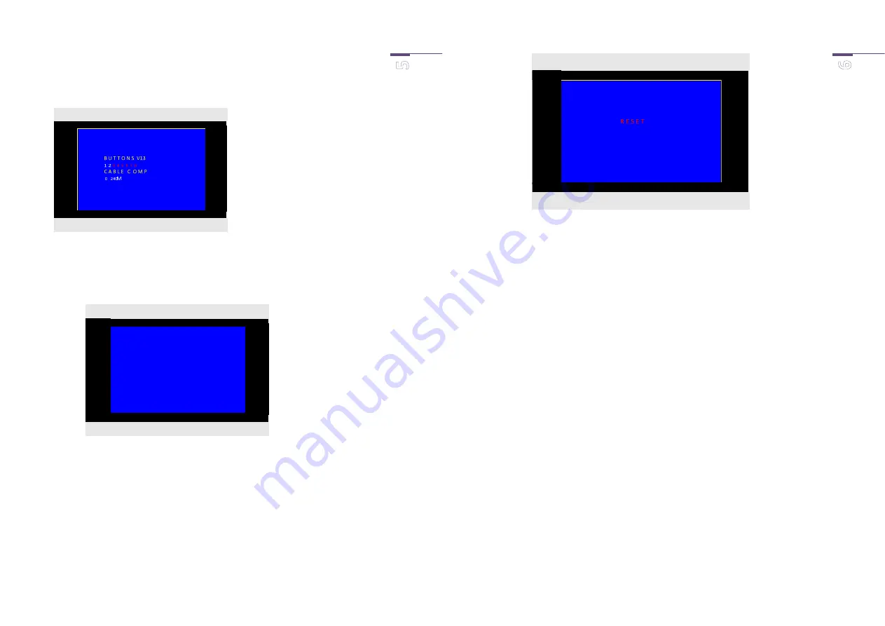
make sure that the screen is blank.
•
RESET by pressing BUTTON 1 for 5 seconds, in which case you will hear 2 short beeps.
Note: this procedure will not reset the colour and contrast settings.
3.
Installation
The FT20CC can be installed in 3 ways:
1.
Tabletop mounting: screw in the base provided, below the screen.
2.
Surface-mounted on the wall: release the black sides of the screen and the 4 crosshead screws in
the screen. You can now take off the aluminium backing plate of the screen. Drill through the two
pre-drilled holes, and fix the back plate on the wall. Be careful not to use oversized screws, as
these could damage the circuit board.
3.
As built-in model: with optional installation casing FT20CCF
The installation casing is flush-mounted in the wall. Keep in mind plaster work that may be done
subsequently. Remove the black sides of the screen and the 4 crosshead screws in the screen. You
can now take off the aluminium backing plate of the screen. Drill through the two pre-drilled
holes and secure the round-head bolts provided, with the round heads on the back. Reassemble
the screen and then click it into the installation casing.
Reposition the sliding portion of the installation casing if the casing was installed too deep inside
the wall.
BUTTON 2 (not applicable)
BUTTON 1 (reset)


