


48
48
Se
rv
ic
e
4.
As a further check, close the manual gas valve. The
FLAME LED goes out, followed by the MAIN and PILOT
LED, the red ALARM LED lights. Open manual gas valves.
Reset controller, which in turn resets FSR.
5.
For further information see the Honeywell 7800 series
RM7895A Relay manual in the component bulletins
section at the end of this manual.
J.11 Flame Signal
NOTE:
Flame signal strengths:
GOOD - 2.5V or greater, fluctuating less than 0.5V
WEAK – between 1.2V and 2.5V and / or fluctuating
more than 0.5V
INSUFFICIENT – below 1.2V
1.
The flame signal strength can be monitored using a
voltmeter set to measure 0 - 10V DC, or using the plug in
Honeywell display module.
2.
When using a voltmeter, insert the red lead into the
positive (+) jack and the black into the negative of the
flame signal amplifier located on beneath the FSR.
3.
Voltage is 0.0 with no flame, and a maximum of 5V with
flame.
4.
Signals between 1.2V to 2.5V and / or fluctuating more
than 0.5V are weak. They allow the heater to continue to
operate, however investigation and probable maintenance
of flame rod, wiring, manifold pressure and burner is
required. Expect irregular nuisance shutdowns.
5.
Flame signals dropping below 1.2V cause the FSR to
extinguish the burner and indicate alarm.
6.
Inspection and probable maintenance of flame rod, wiring,
pressure and burner is required.
J.12 Air Switch
1.
To check the air switch operation, while operating the
unit, block 80% of the air intake screens openings with a
sheet of cardboard. The heater continues to operate.
2.
Now block 90%. The FSR extinguishes the burner and
indicates alarm.
3.
Remove the blockage and reset the controller. The heater
starts.
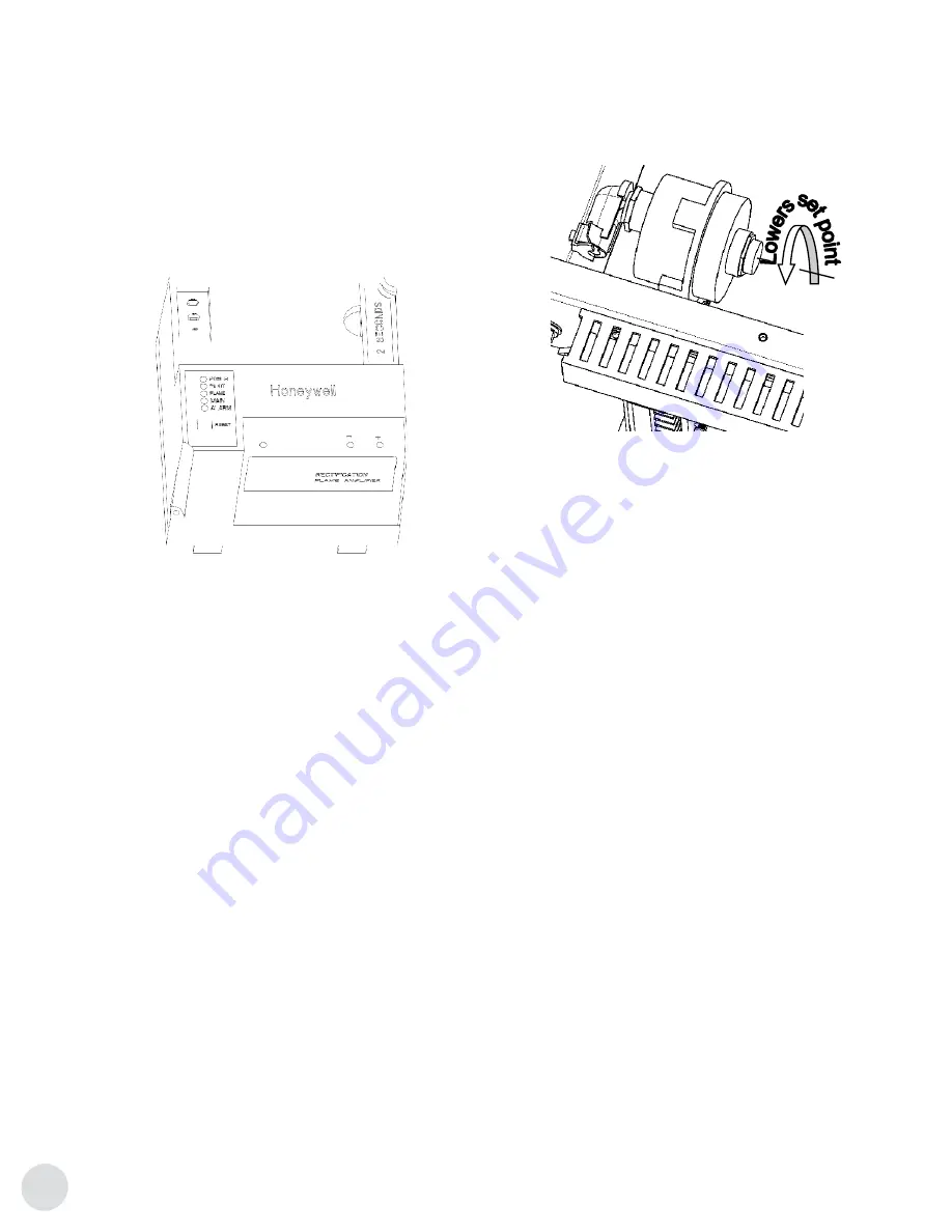
J.13 Air Switch Calibration
1.
With the heater operating, remove the red dust cover
cap on the air switch set screw, and turn the set screw
counter clockwise to lower the set point. Block 90% of
the air intake with cardboard.
2.
Raise the set point by turning the screw clockwise until the
switch opens and causes the FSR to safety shutdown.
3.
Remove blockage and reset FSR.
J.14 High Temperature Limit
1.
Turn the mode selector switch “OFF”.
2.
Open the thermostat box located on the sensor duct.
Disconnect the blue and black leads of the cycling
thermostat.
3.
Use a jumper and short them together.
4.
Turn the heater on, “MANUAL”, and let it run.
5.
Increase the manifold pressure to the maximum rated
setting. Once the air temperature exceeds the 216°C
(420°F) set point, the controller removes the request for
heating, HEAT LED off, indicates alarm with STATUS LED
red, FSR ALARM LED red, ALARM LED red and HIGH LIM
LED alternating. The fan continues to run for 4 minutes of
post purge.
6.
Return the mode selector switch to desired mode.
7.
Reconnect the cycling thermostat and reset the controller.
Summary of Contents for Hellfire 900
Page 26: ...26 26 Figure 3 155 Clearance Figure 2 140 Clearance Installation...
Page 27: ...27 27 Figure 4 155 Clearance Turned 90 Degrees Installation...
Page 37: ...37 37 Heater Specifications THERMON HEATING SYSTEMS INC H 9 SchematicsMaintenance...
Page 38: ...38 38 Heater Specifications THERMON HEATING SYSTEMS INC...
Page 39: ...39 39 Heater Specifications THERMON HEATING SYSTEMS INC...
Page 40: ...40 40 Heater Specifications THERMON HEATING SYSTEMS INC...
Page 41: ...41 41 Heater Specifications THERMON HEATING SYSTEMS INC...
Page 42: ...42 42 Heater Specifications THERMON HEATING SYSTEMS INC...
Page 54: ...54 54 NOTES...
Page 55: ...55 55 NOTES...


