

www.fastech-motions.com - 30
*1 : Value in the columns are in relative units.
They only show the parameter changes
depending on the switch’s position.
*2 : Default = 3
*1 : Default = 0
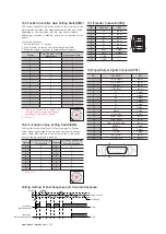
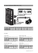
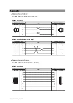
16.5 Position Controller Gain Setting Switch(SW2)
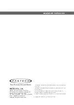
16.6 In-Position Value Setting Switch(SW4)
The Position Controller Gain Switch allows for the correction of the
motor position deviation after stopping caused by load and friction.
Depending on the motor load, the user may have to select a
different gain position to stabilize and to correct positional error
quickly.
To tune the controller
1. Set the switch to“0”position.
2. Start to rotate the switch until system becomes stable.
3. Rotate the switch 1~2 position to reach better performance.
To select the output condition of In-Position signal, In-Position
output signal is generated when the pulse number of positional
error is lower than selected In-Position value set by this switch
after positioning command is executed.
Position
In-Position Value[Pulse]
Fast Response
Position
In-Position Value[Pulse]
Accurate Response
0
*1
0
8
0
1
1
9
1
2
2
A
2
3
3
B
3
4
4
C
4
5
5
D
5
6
6
E
6
7
7
F
7
10 1
20 11
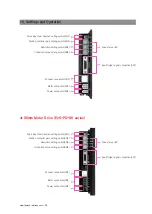
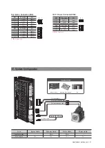
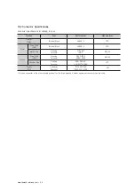
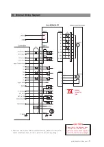
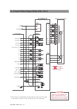
16.8 Input/Output Signal Connector(CN1)
NO.
Function
I/O
1
CW+(Pulse+)
Input
2
CW-(Pulse-)
Input
3
CCW+(Dir+)
Input
4
CCW-(Dir-)
Input
5
A+
Output
6
A-
Output
7
B+
Output
8
B-
Output
9
Z+
Output
10
Z-
Output
11
Alarm
Output
12
In-Position
Output
13
Servo On/Off
Input
14
Alarm Reset
Input
15
Open Collector Input
Input
16
BRAKE+
Output
17
BRAKE-
Output
18
S-GND
Output
19
EXT_GND
Input
20
EXT_24VDC
Input
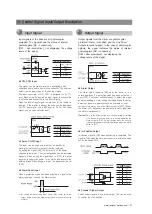
16.7 Encoder Connector(CN2)
NO.
Function
I/O
1
A+
Input
2
A-
Input
3
B+
Input
4
B-
Input
5
Z+
Input
6
Z-
Input
7
5VDC
Output
8
GND
Output
9
F.GND
----
10
F.GND
----
2
10
1
9
Position
Time Constant of the
Integral part
Proportional Gain
*1
0
1
1
1
1
2
2
1
3
3
*2
1
4
4
1
5
5
2
1
6
2
2
7
2
3
8
2
4
9
2
5
A
3
1
B
3
2
C
3
3
D
3
4
E
3
5
F
3
6
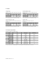
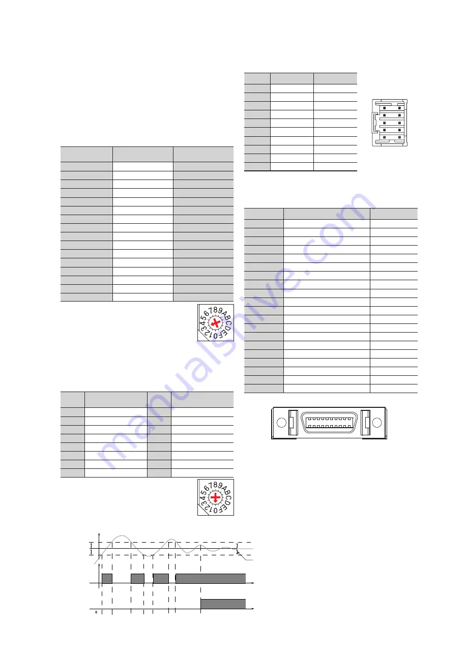
Setting method of Fast Response and Accurate Response
In-Position
(Fast Response)
Position
In-Position
(Accurate Response)
Target Position
In-Position
Time
Time


