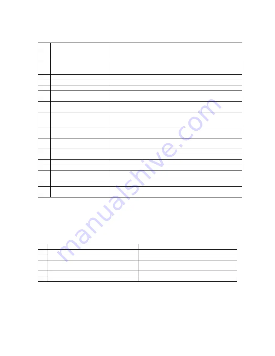
background image


9

Programming Menus 
 

CHANGE PRICE

:


Allows the price to be changed.


SALES METERS

:


Allows sales data to be viewed. The total sales meter is non-
resetable, and offers a total sales and unit counter.


EDIT SELECTION

:


Allows existing selections to be edited: Price, Product Height (1-
4 in.) and Bin (adjust bin location, add bins to the selection 
number or change bin height).


CREATE SELECTION

:


Allows a selection to be created.


DELETE SELECTION

:


Allows a selection to be deleted.


SELECTION NUMBERS

:


Allows programmed selection numbers to be viewed


SET DATE

:


Allows date to be set or viewed.


SET TIME

:


Allows time to be set or viewed. Military / 24 hr time.


SERVICE PHONE #: 

Allows service phone number to be set. The number is 
displayed when the machine is out-of-order.


10  SALES PIN CODE

:


Allows pin code to be set and viewed for machine auditing. 
Sales meters can be viewed without opening the door. 
DEFAULT: #, *, 1, 2, 3, 4


11 VEND 

BLOCK: 

Allows machine to be disabled for predetermined periods of 
time.


12  VEND BLOCK PIN 

CODE: 

Allows pin code to be set and viewed and allows access to vend 
block times from outside the machine.


13 HEALTH 

TIMER: 

Allows the health sensor to be bypassed for up to 4 hours.


14 PROGRAM 

VERSION: 

Displays current version of operational software (e-prom).


15 DISPLAY 

LANGUAGE: 

Allows programmer to choose language displayed on screen.


16 LINE 

MODE: 

Allows machine to detect a customer line and shorten vend time.


17 MACHINE 

SERIAL 

NUMBER: 

Allows programmer to program serial number of the vendor for 
machine identification during DEXing.


18  GROUP SALES OPTION: 

Allows programmer ability to have up to four metered accounts.


19  TOKENS & COUPONS: 

Allows for the use for tokens and coupons. 

20 FIELD 

TEST: 

Allows all functions of the machine to be tested. 


GETTING STARTED; CREATING SELECTIONS 

1)  Before creating a selection, the front product display must be setup. Product and bins must 

be preloaded in the 

machine

2)  In Service Mode, press the “*Next” key and scroll to “4 CREATE SELECTION”. "4 CREATE 

SELECTION" allows new selections to be created (Note: do not start programming yet). 

3)  Menu item "4 CREATE SELECTION" will require the following information to be entered: 


Enter a selection number: 

A1 to D1 

Enter the price: 

$.05-$9.95 

Enter the height of the product: 

1-4 inches 

Move the robot over center of the product:


Controls on service keypad: front/back, 
left/right, down/up 

Enter the length of the bin: 

Short/tall 

Add more than one bin for the selection: 


Yes/No 


4)  In the Programming Menus section, locate the flow chart for the menu item "4 CREATE 

SELECTION" and follow the step-by-step instructions for programming new selections. 

5)  Once selections have been programmed, use the other available menu items to edit and 

select operating preferences. Refer to Menu Item Description for an overview of each menu 
item and its features. 

6)  Once programming is complete, it is important to perform a test to make sure that the 

machine 

was programmed correctly. By pressing “Free Vend” on the Service keypad, the 

machine 

will 

Summary of Contents for F820

Page 1: ...F820 Service and Parts Manual Ver FC031504...

Page 2: ...s Option 11 Set Time 22 23 Tokens Coupons Field Test F Free Vend Test Vend III Troubleshooting A Glossary Of Useful Terms B Error Reporting Features 1 Non Fatal 2 Fatal C Order Of Operation 1 Initiati...

Page 3: ...range of operation temperature is 25 F 31 C to 15 F 9 C at 70 F 21 C ambient The standard chest freezer inside the F820 does not self defrost automatically The freezer chest requires maintenance when...

Page 4: ...FFC cables with the corresponding connector number printed on the intermediate board J 24 J 25 Mark the 2 pin connector which plugs into J 28 VAC sensor below the ground wire Remove the 2 pin connecto...

Page 5: ...the serial number error code and a description of the problem available before calling The toll free number to call is 1 888 441 3278 and press 2 for the service department If your meter does not have...

Page 6: ...of the cabinet 3 Robot carriage moves towards the FRONT of the cabinet considered the HOME position If the robot does not move or follow the Homing Sequence 1 There may be setup errors or shipping da...

Page 7: ...ity of all ice cream novelties Spacers and inserts are provided for products such as ice cream cones sandwiches and Snickers However if there are products that require special bins contact the FASTCOR...

Page 8: ...Key Press a key and the screen will change to Testing External RAM for about one second 5 The screen will display Checking Real Time Clock Disconnect the power and return the dipswitch settings to no...

Page 9: ...en vend time 17 MACHINE SERIAL NUMBER Allows programmer to program serial number of the vendor for machine identification during DEXing 18 GROUP SALES OPTION Allows programmer ability to have up to fo...

Page 10: ...clear all bin errors and Out Of Product bins press Load and then Close on the service keypad The display must be in the main menu for this to work ie 1 CHANGE PRICE 5 The machine is ready to be edite...

Page 11: ...ext Yes a Press the Yes key to alter Product Height A1 Height 1inch 1 4 Next Yes b Press the Next key for heights 1 4 inches Press Yes key to enter new product height A1 Height 3inches Accept No Yes c...

Page 12: ...ter of product selected Press the back button first Holding down to accelerate pulse your finger on button to move in 1 16 increments Move robot right then drop picker head to verify that it is center...

Page 13: ...e Yes key to enter set date menu Enter Date 01 01 03 Abort Enter b Type new date press the Enter key to store Date format MM DD YY Enter Date 01 05 03 Accept No Yes c Press the Yes key to store new da...

Page 14: ...be off and press the Enter key Mon Blk 1 On 09 00 military time Accept No Yes e Press the Yes key to store the time Mon Blk off _ _ _ _ Abort Enter f Type the time you want vending to resume and pres...

Page 15: ...lt is ON Display Programming Instructions 16 LINE MODE Next Menu Yes a Press the Yes key LINE MODE ON Scroll A Abort Enter b Press the key to select the desired option c Press the key to confirm the s...

Page 16: ...r additional blocks of time if desired if not press Abort key to exit screen Press A key to exit next screen and A once more to return to main menu 19 TOKENS COUPONS Enables the option to accept token...

Page 17: ...Point Coordinates where the robot drops product into the product delivery chute located in the front center area of the cabinet VAC Error VAC key Log used by the computer to store fatal machine errors...

Page 18: ...ontroller fails to see encoder pulses on the X axis after 3 unsuccessful tries This error typically occurs during product retrieval or delivery Front Back F B Encoder Error Occurs when the controller...

Page 19: ...oordinate 3 Robot Moves Right The L R Motor moves the robot to the right on the X axis As the robot leaves the L R Home position the controller looks for the L R Home Switch to open to begin counting...

Page 20: ...obot reaches the full up position triggering the Z Home Switch If The controller times out before a closed U D Home Switch signal is detected The vacuum motor is shut down The machine is put out of or...

Page 21: ...tion of the product drop point If Encoder pulses are not seen for a period of time the robot will move straight back returning to the Y Home Position located at the front of the cabinet The robot will...

Page 22: ...J5 and J24 If the connections look good check continuity from computer board J5 pins 7 8 to int board J5 pins 7 8 and from int board J24 pins 1 2 to the two wires at the left right home switch Left R...

Page 23: ...nt Faulty computer board When replacing the computer board note the software on the defective board as well as the position of the jumper JP1 Make sure the software and jumper postion are the same Inc...

Page 24: ...Turn power off Check the computer board connection labeled J18 the intermediate board connections J18 and J29 and the plug at the front back motor If the connections look good check continuity from c...

Page 25: ...he same Incorrect software or jumper may cause the machine to function improperly Turn power off Locate the computer board connection labeled J5 Using a jumper wire or small paperclip connect pins 3 4...

Page 26: ...open switch Turn the power off Disconnect the freezer door open switch Using a jumper wire or small paperclip connect the two wires that the switch plugs into Close the freezer door Turn power on and...

Page 27: ...oken teeth Manually move the lift arm up and down Check for binding If a replacement gear is necessary PN 49500406 Check connection from the Computer board to the Freezer Door Motor Turn power off Che...

Page 28: ...en the screws on the switch slide it back towards the freezer and retighten Check connection from the controller board to the freezer door closed switch Turn power off Check the computer board connect...

Page 29: ...J25 and the plug at the freezer door motor If the connections look good check continuity from computer board J18 pins 1 3 to int board J18 pins 1 3 and from int board J25 pins 1 5 to the freezer door...

Page 30: ...r postion are the same Incorrect software or jumper may cause the machine to function improperly Set your multi meter to DC Volts On the computer board connector J5 across pins 15 16 should be 5 volts...

Page 31: ...down If not replace the U D motor If the motor has a small pigtail harness use PN 49505565 If the connector is right on the motor use PN 49505555 U D Encoder Error During the vend cycle the robot hose...

Page 32: ...rd note the software on the defective board as well as the position of the jumper JP1 Make sure the software and jumper postion are the same Incorrect software or jumper may cause the machine to funct...

Page 33: ...machine Leaking vacuum valve assy Inspect the assembly and fix the cause of the leak Bin Errors Robot dropping product Binding in the vacuum valve assembly Inspect the assembly and fix the cause of t...

Page 34: ...ns replace the picker head assembly PN 39510620 Short in the harness from the picker to the intermediate board Remove machine power Disconnect the hose from the picker Unplug the 2 pin connector Unplu...

Page 35: ...sensor PN 19610510 Health Sensor Active Occurs when the health sensor opens Usually at 10 degrees Faulty intermediate board faulty computer board When replacing the computer board note the software o...

Page 36: ...pin connectors from the interface board 3 Label and remove the following connectors from the computer board a door 2 pin top left twisted wires b triacs left side lower 12 pin w wires at location 1 an...

Page 37: ...andoffs positioning it the same way as the old board 10 Remove the harnesses from the original board one at a time and install them on the new board being careful to install them in the correct positi...

Page 38: ...the black weather proof cover over the boards being careful not to pinch any of the wiring Note The 2 dipswitch counting from the bottom of the block is to enable a two character selection number and...

Page 39: ...ove the three 3 16 phillips screws holding the motor in place Reinstallation 1 Put new motor in place and line up all three screw holes 2 Install the three 3 16 phillips screws but don t tighten them...

Page 40: ...able 5 Mount the motor bracket assembly using the two 7 16 bolts Don t tighten them yet 6 Slide the assembly up so that the gear mesh is tight then back off 1mm and tighten the 7 16 bolts Ideal gear m...

Page 41: ...r to the assembly Installation 1 Connect the ribbon cable to the new motor 2 Mount the new motor using the three 3 16 bolts screws Do not tighten them yet 3 With the toothed arm in place put the white...

Page 42: ...ip into the hose where they can t be reached 6 Plug the connector into the new picker head 7 Tie wrap the wires to the picker head as they were before 8 Slide hose down into place and tie wrap the hos...

Page 43: ...k and have someone feed the wires through the hole as you carefully pull the other end through This will route the new wires to where the old wires were 7 Once the wire is fed under the freezer and to...

Page 44: ...the door top to break the silicon seal 7 Lift the Front Door Bubble Panel up by grabbing the delivery door opening and pull up and out 8 Before reinstalling the new Front Door Bubble Panel remove the...

Reviews: