background image

FV3000


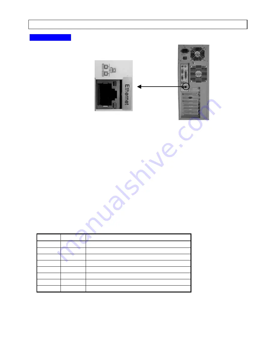
4.3.6 ETHERNET Connector 


【 FV3000-W2K 】 


The ETHERNET connector is for connecting with a LAN cable. 
This connector is for connecting the UTP cable of 10BASE-T/100BASE-TX. This port automatically detects 
communication speed (10Mbps/100Mbps) and communication mode (Full Duplex/Half Duplex), and selects the best 
connection. 
 
Select Category 5 cable or larger to operate a network with 100Mbps. If a Category3 or Category4 cable is used, 
some trouble (data loss or other) may occur, even though it appears to be all right at the beginning. Although 
the Category3 and Category4 cables are available when connecting the network with 10Mbps, the use of a Category5 
cable is recommended in view of the reliability for factory automation use. 
 
Note that a distance between the system and the line concentrator (HUB) is not allowed to be over 100m. 


ETHERNET connector has 2 LEDs to express the current situation. 
LAN Link/Act LED(Green) 

:It is connecting with data link (connecting with HUB directly), while the indicator 

is ON. Data is sending or receiving while the indicator light is blinking.  
LAN Speed LED(Orange) 

:The indicator is ON in the case of 100Base-T, and the indicator is OFF in the case 

of 10Base-T.  


ETHERNET Connector 

Pin No. 

Direction

Description of Signal 

TD+(Transmit Data+) 

TD-(Transmit Data-) 

RD+(Receive Data+) 

N/A 

Reserved 

N/A 

Reserved 

RD-(Receive Data-) 

N/A 

Reserved 

N/A 

Reserved 

*“I”indicates Input,“O”indicates Output, “I/O”indicates Input/Output, “N/A”indicates Power or Reserved. 

* The RJ45 connector is used. 


-  - 

33

Summary of Contents for FV3000-W2K

Page 1: ...General purpose Image Processing System FV3000 Series FV3000 Instruction Manual First Edition FAST CORPORATION ...

Page 2: ... of this manual unclear points errors or omissions may nevertheless remain Please contact us if you would like to make any comments 4 Notwithstanding the statements in Items 2 and 3 above FAST CORPORATION will not be held liable under any circumstances for any consequences arising from use of this product 5 FAST CORPORATION assumes no liability for any damage s arising from the improper use or the...

Page 3: ...loss or damage resulting from the neglect to follow these instructions The symbols below are used on the product Handle with Care Functional Ground Terminal Do not use as a protective ground terminal Alternate Current Power ON Power OFF Regulations on Export To export this product refer to the regulations in the Foreign Exchange and Foreign Trade Control Law and follow the necessary legal procedur...

Page 4: ...in minor injury or property damage Caution Improper handling of the product may result in minor injury or property damage Provides information for avoiding trouble of the product or ensuring the product to work properly Note Note provides important information in handling this product ...

Page 5: ...is labeled on the front of the system FV3000 Env Mod Per Env ironment Software Operation Environment When FV3000 W2K is purchased the product name is described as W2K When FV3000 DOS is purchased the product name is described as DOS Mod el Product Model Form The model of this product is A1 ATX specification No 1 Per formance Performance This product uses a CPU of P4 XX Pentium 4 XXGHz XX indicates...

Page 6: ... illegal action Software License RTL FVX Standard Pack RTL or RLT WIN Licenses of attached software products of the FV3000 W2K Execution modules related to FVX Licenses which require purchase separately FV3000 DOS 1 MS DOS License Agreement FV3000 DOS uses MS DOS for system startup file system and other operations MS DOS License Agreement Japanese English is supplied with the product Read the agre...

Page 7: ...e without license is considered an illegal action 2 Please register to become a user Please fill in the user registration form attached to this product and return it to FAST Corporation We provide user support services and upgrade information There is no need to re register if you are already a registered member ...

Page 8: ......

Page 9: ...pearance 23 4 1 1 Air Intake Ventilation Holes 23 4 2 Front Panel 24 4 2 1 POWER HDD RESET 24 4 2 2 Flash File Unit Maintenance Panel 26 4 2 3 CD ROM Drive Floppy Disk Drive 27 4 3 Rear Panel 28 4 3 1 POWER Switch 29 4 3 2 Power Connector 30 4 3 3 Functional Ground Terminal 30 4 3 4 RS232C Connector CH0 CH1 31 4 3 5 Parallel Link Port P LINK 32 4 3 6 ETHERNET Connector 33 4 3 7 VGA Connector 34 4 ...

Page 10: ...Contents 2 5 6 Board Installation Guidelines 42 6 Cable Wiring Diagram 45 6 1 RS232C Cable Optional 45 6 2 Parallel Link Cable Optional 46 7 Parts Life spans 47 ...

Page 11: ...ing Manual included in this manual 1 copy Handling Manual for Installed Board s FV3000 Handling Manual Handling Manual for Installed Board s These provide important information necessary for ensuring the safe and proper use of the product This manual may not contain the latest information due to changes of the product s specifications You can download the latest manual from our website http www fa...

Page 12: ...W2K Please read this guide before use This manual may not contain the latest information due to changes of the product s specifications You can download the latest manual from our website http www fast corp co jp 3PIN Power Cable 1 Cable approx 3m 125V 10A AC3P 2PIN Conversion Adapter 1 cable 125V 15A MS DOS License Agreement FV3000 W2K User s Guide ...

Page 13: ...FV3000 3 Mounting Fittings 2 plates with six 3 mm screws ...

Page 14: ...apctFlash Card or the data on the card is damaged due to a malfunction of the device or improper operation Please ask our sales office or agent for details All the data on the CompactFlash Card OS and other software programs are made from master data that has been checked for viruses Hard Disk Drive 2GB FV3000 DOS The installed hard disk drive s capacity is 2GB but available drive capacity does no...

Page 15: ...he currently available devices may differ from the one above Note that Japanese keyboard 106 or 109 keys may be selected Slide Rail User setting of the slide rails to be attached to the side of 19 inch rack EIA JIS standard makes it easier to store or take out the system Manufacturer Accuride Japan Co Ltd Model No 305A 18 Withstand load 53kg pair RS232C Cable There are a wide variety of RS232C cab...

Page 16: ... desired resolution display LAN Cable RJ45 Category 5 FV3000 W2K Under the circumstances of a 100BASE TX or 10BASE T network a cable from category 5 or enhanced category 5 is recommended to ensure the reliability for factory automation LAN cables are categorized by grade depending on speed Category 3 10M bits sec Category 5 100M bits sec Enhanced Category 5 1G bits sec Higher categories offer high...

Page 17: ... and White Video Monitor FV3000 DOS The images will be displayed full screen The monitor may need adjustment to view the image edges This adjustment will be easily made if a monitor supporting Under Scan is used 7 ...

Page 18: ...FV3000 8 ...

Page 19: ...in the rack JEIDA 63 2000 Class B compliance Use the following formula for calculating the system s calorific power Input current A Input voltage V Calorific power kcal h If you do not know the input current select a rack up to the calorific power of 258 kcal h Note that connection parts and connectors are not described in this manual The system height includes 6mm rubber feet For replacement filt...

Page 20: ...512MB Chipset Intel 865G Number of PCI bus slots 5 Frame grabber Up to 2 boards Video board Up to 1 board Optical Isolated I O board Up to 2 boards VGA Built in chipset can not be used in FV3000 DOS LAN Onboard 10 100MBase can not be used in FV3000 DOS RS232C Connector 1 200 115 200bps 2ch Parallel link connector For downloading User s program 1ch Mouse connector PS 2 1ch Keyboard connector PS 2 1...

Page 21: ...eted otherwise the file unit HDD may have a terminal breakdown FV3000 DOS 1 How to Turn OFF the System Turn OFF the POWER switch on the front or the AC power switch on the back after verifying that the HDD display LED light is out 2 Restoring Power to the System Press the POWER switch to start the system when the AC power switch is ON Please wait for more than 10 seconds to restore power to the sy...

Page 22: ... installed boards in the system FV3000 W2K PCI Bus Specs Optical Isolated I O Board File Unit PCI Bus Specs Frame Grabber Motherboard Main Memory CPU VGA Monitor Output RS232C PS 2 Trackball PCI Bus Is an available option IDE I F PS 2 Keyboard Is the provided system Camera Input ETHERNET 12 ...

Page 23: ...lated I O Board File Unit PCI Bus Specs Frame Grabber Motherboard Main Memory CPU RS 232C PS 2 Trackball PCI Bus Camera Input IDE I F PCI Bus Specs Video Board Monitor Output Parallel Link Port は Is the provided system Is an available option 13 ...

Page 24: ...FV3000 14 ...

Page 25: ... Mounting Fittings The air intake and exit are ventilation holes to prevent heat built up inside the machine If these holes are blocked it may cause the system to malfunction or fire Leave a space of at least 100 mm from the holes Caution Avoid installing the FV3000 in the following places The ambient temperature falls below 5 C or exceeds 40 C The temperature fluctuates drastically and condensati...

Page 26: ...m vertically 1 Turn off the system s power switch 2 Unplug all the cables from the system 3 Turn the machine upside down to place the rubber feet facing up 4 Remove the rack mounted fittings as needed 5 Fasten the mounting fittings to the machine tightly using the screws Screw positions for fastening the mounting fittings Front After installing Front Rack mounted fittings ...

Page 27: ...de down and unscrew the screws in the middle of the rubber feet to remove them 4 Fasten the mounting fittings to the machine tightly using the screws 17 Screw positions for fastening the mounting Front fittings After installing Front Caution If the FV3000 is not fastened it may topple and be damaged Be sure to fasten the machine using the mounting fittings ...

Page 28: ...les from the system 3 Fasten the mounting bracket for slide rails to both side of the machine tightly using the provided screws 4 Fasten the mounting bracket on the rack and insert the rails Screw positions for fastening the slide rail Front Mounting Image Front Mounting Image Caution Note that the load capacity per two slide rails is 53kg If the system overweighs this load capacity it may topple ...

Page 29: ... the protective ground terminal Necessity of Protective Grounding Do not cut off the protective ground conductor inside or outside the FV3000 or disconnect the protective ground wiring to avoid hazards Warning Be sure to observe the following to prevent damage to the machine electrical shock or fire Be sure to disconnect the power cable and connection cables before connecting or disconnecting the ...

Page 30: ...e front panel to take off the metal cover and remove the filter 3 Vacuum up the dust from the filter or blow off the dust using an air duster compressed air 4 Put the cleaned filter back into place reversing the procedure 2 When reconnecting connectors check that they are connected correctly Screws for fastening the mounting fittings of the air intake panel Caution Do not use the FV3000 when the f...

Page 31: ...le data is accessed Be sure to back up data on the card onto a PC or other medium Use of CompactFlash Card for Maintenance is Recommended If the files on the CompactFlash Card are destroyed for some reason the application program can be restored However if the FV3000 system is affected the CompactFlash Card may need replacement We recommend you buy a CompactFlash Card for maintenance so that you w...

Page 32: ...FV3000 22 ...

Page 33: ...e a large amount of heat make sure that the fan is running Do not open the intake except for replacement of the dust filter Caution There must be a space of at least 100mm from the air intake and other foreign objects Do not block the intake If the air intake is blocked the internal temperature will rise excessively resulting in thermal runaway damage or fire Also do not put metallic flammable or ...

Page 34: ...ESET switch Resets the system Press the switch using a thin cylindrical object like a toothpick or the tip of ball point pen Function of POWER Switch FV3000 W2K The POWER switch is equivalent to a general computer power switch If you press this switch while the power switch on the rear is ON it will turn OFF the system In this case press the POWER switch again to restart the system ON OFF OFF BP S...

Page 35: ...r is ON it will turn OFF the system In this case press the POWER switch again to restart the system BP SW OFF ON OFF BP SW OFF OFF POWER Switch POWER Switch BP SW ON BP SW ON BP SW ON BP SW ON BP SW OFF OFF BP Back Panel Never press the POWER switch while the system is running or the HDD indicator is ON This may cause files to be destroyed 25 ...

Page 36: ...te that this panel is not equipped with the FV3000 W2K Caution Behind the maintenance panel the Flash File Unit CompactFlash Card is installed When opening and closing the panel for maintenance observe the following precautions Never remove or insert the CompactFlash Card while the power switch is ON power is supplied This may cause damage to the CompactFlash Card and the FV3000 If the CompactFlas...

Page 37: ... 4 2 3 CD ROM Drive Floppy Disk Drive FV3000 W2K These are the CD ROM drive and floppy disks drive for working on Windows 2000 Professional FV3000 DOS This is a floppy drive with 2 modes 3 5inch and 1 44MB 27 ...

Page 38: ...lots for boards provided by FAST Camera control connector EXT CONTROL PS 2 connector MOUSE Rear fan VGA connector Not available for the FV3000 DOS Note The camera control connector EXT CONTROL is provided only when the RICE 001 a is selected The camera control connector EXT CONTROL cannot be used when two RICE 001a boards are installed Refer to the board manual for descriptions of each connector B...

Page 39: ... switch to use the FV3000 Turn the POWER switch to ON to start the system Never turn OFF power while the system is running or the file unit is being accessed The HDD indicator LED is ON Otherwise it can cause the data corruption FV3000 W2K Never turn OFF the POWER switch without shutdown Otherwise it can cause the data corruption 29 ...

Page 40: ...ng to a power source over 125V Refer to 2 3 How to Turn OFF the System about turning OFF the power Refer to 3 4 Power Supply Wiring about power cable connections 4 3 3 Functional Ground Terminal This terminal is used to keep the same ground level of the FV3000 and the floor or a rack The signal ground SG and the frame ground FG of the casing are connected to the ground terminal Generally the SG of...

Page 41: ...n the PC s specifications Half duplex Communication Available for communication with the PC or the 90X series Compatible with the PC 9800 series and PC AT compatible machine Host communication program or C LINK libraries RS232C CH0 CH1 Connector Mating Screw Inch Screw Pin No Signal Direction Description of Signal 1 Reserved 2 RXD Receive Data 3 TXD Transmit Data 4 DTR Indicates that the FV3000 is...

Page 42: ...E Data Capture Synchronizing Signal 2 Data Bit 0 Transmit Data Bit 0 3 Data Bit 1 Transmit Data Bit 1 4 Data Bit 2 Transmit Data Bit 2 5 Data Bit 3 Transmit Data Bit 3 6 Data Bit 4 Transmit Data Bit 4 7 Data Bit 5 Transmit Data Bit 5 8 Data Bit 6 Transmit Data Bit 6 9 Data Bit 7 Transmit Data Bit 7 10 ACK Completion of Data Input 11 BUSY Printer cannot receive data 12 PE Paper End 13 SLCT Selectiv...

Page 43: ...e is recommended in view of the reliability for factory automation use Note that a distance between the system and the line concentrator HUB is not allowed to be over 100m ETHERNET connector has 2 LEDs to express the current situation LAN Link Act LED Green It is connecting with data link connecting with HUB directly while the indicator is ON Data is sending or receiving while the indicator light ...

Page 44: ... Signal 1 O Red Data 2 O Green Data 3 O Blue Data 4 N A Reserved 5 N A Ground 6 N A Ground 7 N A Ground 8 N A Ground 9 N A Reserved 10 N A Ground 11 N A Reserved 12 N A Reserved 13 O HSYNC 14 O VSYNC 15 N A Reserved I indicates Input O indicates Output I O indicates Input Output N A indicates Power or Reserved The HD 15 pin DSUB female connector is used 34 ...

Page 45: ...ion of Signal 1 DATA MOUSE Communication Data 2 Reserved 3 GND Power Supply Signal Ground 4 5V Power Supply 5V 5 CLK MOUSE Synchronizing Clock 6 Reserved indicates Output indicates Input indicates Two Way sending The 6 pin mini DIN connector is used KEYBOARD Connector For use by the FV3000 W2K only Pin No Name of Signal Direction Description of Signal 1 DATA MOUSE Communication Data 2 Reserved 3 G...

Page 46: ...FV3000 36 ...

Page 47: ...dered surfaces Make sure that the power of the machine is OFF when removing or installing a board Refer to 2 3 How to Turn Off the System Make sure that the power cable and all other cables are disconnected from the machine If you try to remove or install a board with the power ON or with any of the cables connected CMOS settings may be destroyed or the circuits of the board or the machine may be ...

Page 48: ... Remove the two screws on the rear panel allowing you to slide open the cover 1 Turn OFF the POWER switch of the FV3000 2 Disconnect all the cables from the FV3000 3 Remove the screws as shown below 4 Slide open the cover Remove these screws 38 ...

Page 49: ...d make preparations for installing the board Open the main unit cover If cables obstruct the board disconnect the cables Remember where each cable is connected Be careful not to access the cables when disconnecting them Refer to 5 2 How to Open the Main Unit Cover 4 Install the board in position Install the board while referring to the manual for the board After fitting the board into the slot fas...

Page 50: ...C3310 A For High speed High resolution Camera PCI FHC3310CL For High speed Camera Link Interface Camera PCI FHC3321 A For High resolution Digital Camera PCI FHC3322AFA For Image Quality Improvement Camera PCI FHC3328 For Color Camera PCI FIO01 Optical Isolated I O Board PCI FV3000 DOS Incorporable board list for the FV3000 DOS Product Name Functions Bus Connector PLUM 001 For Monitor Display based...

Page 51: ...able CAMERA EXT_IF VIDEO_IN FHC330A NC FHC3310 A CAMERA_IF FHC3321 A CAMERA_IF External Trigger IN FHC3328 CN3 CN4 VIDEO_IN FHC3322AFA External Trigger IN VIDEO IN FHC3310CL CN2 CN1 RICE 001 a CH0 CH1 CH2 CH3 FVC01 CH0 CH1 CONT FVC02 CH0 CH1 CONT FVC 02 FVC04 CN1 CONT FVC05 CH0 CH1 CONT FVC 05 CN2 CN1 FVC06 CN4 CN3 This section shows only the shape of each board Refer to the manual for each board ...

Page 52: ...ng 2 RICE 001a boards an EXT CONTROL connector cannot be supplied The FVC06 board requires 2 slots Refer to the manual for each board about their specifications In addition to that mentioned above there are the following restrictions when using the FAST Vision Library for Windows Only identical boards can be inserted into the device When using RICE 001a boards only 1 of these boards can be inserte...

Page 53: ...bout available libraries Go to our website to download the latest release notes http www fast corp co jp Up to two FVC01 and FVC02 boards can be inserted The following boards cannot be used at the same time RICE 001 a FVC01 FVC02 When using FHC330A FHC3321 A FHC3310 A boards up to 2 boards each or up to 2 boards in combination can be inserted When using the FHC series with RICE 001 FVC01 FVC02 boa...

Page 54: ...FV3000 44 ...

Page 55: ... connecter to 9 pin female connector 4m Female Female XM2D 0901 OMRON or equivalent Mating screw Inch Screw 4 40UNC RS232C Serial Cable 5 45 FV3000 Connected Device Signal Name Pin No Pin No Signal Name 1 1 RxD 2 2 RxD TxD 3 3 TxD DTR 4 4 DTR SG 5 5 SG DSR 6 6 DSR RTS 7 7 RTS CTS 8 8 CTS 9 9 ...

Page 56: ...e XM2A 2501 OMRON or equivalent Mating screw Inch Screw 4 40UNC 3m Parallel Link Cable 1 FV3000 DOS M2 Connected Device Signal Name Pin No Pin No Signal Name data0 2 15 ERROR data1 3 13 SLCT data2 4 12 PE data3 5 10 ACK data4 6 11 BUSY BUSY 11 6 data4 ACK 10 5 data3 PE 12 4 data2 SLCT 13 3 data1 ERROR 15 2 data0 GND 25 25 GND 46 ...

Page 57: ...ected life span is about 3 years when used for 24 hours a day and 30 days a month CPU Cooling Fan Expected life span is about 3 years when used for 24 hours a day and 30 days a month Motherboard Expected life span is about 3 years and a half when used for 24 hours a day and 30 days a month Lithium Battery Expected life span is about 5 years when used for 24 hours a day and 30 days a month Power Su...

Page 58: ...Ellipse hole 4 5x10 22 5 380 450 47 5 173 434 380 6 208 193 Appearance Diagram Vertically Setting ...

Page 59: ...Appearance Diagram Horizontally Setting Ellipse hole 4 5x10 22 5 450 380 173 179 6 428 453 468 ...

Page 60: ...pearance Diagram Rack Mounting Made by Accuride Japan Ellipse hole 7 4 5 x 5 3 Optional Slide rail 305A 18 26 2 450 36 15 9 19 457 2 425 4 412 7 301 6 111 1 25 4 12 7 19 1 466 2 19 1 480 465 428 101 6 170 ...

Page 61: ...n for Internet based services By using the software you accept these terms If you do not accept them do not use the software Instead contact FAST Corporation to determine its return policy for a refund or credit If you comply with these license terms you have the rights below 1 USE RIGHTS You may use the software on the device with which you acquired the software Processor Limit You may use the so...

Page 62: ... these features visit http www microsoft com windowsxp downloads updates sp2 docs privacy mspxT By using these features you consent to the transmission of this information Microsoft does not use the information to identify or contact you b Computer Information The following feature uses Internet protocols which send to the appropriate systems computer information such as your Internet protocol add...

Page 63: ...y copies of the software including the backup copy 8 NOT FAULT TOLERANT The software is not fault tolerant FAST Corporation installed the software on the device and is responsible for how it operates on the device 9 RESTRICTED USE The Microsoft software was designed for systems that do not require fail safe performance You may not use the Microsoft software in any device or system in which a malfu...

Page 64: ......

Page 65: ...V3000 Series FV3000 Instruction Manual First Edition First Printing May 2007 FAST CORPORATION 2791 5 Shimotsuruma Yamato City Kanagawa 242 0001 Japan Phone number 81 46 272 8680 Fax number 81 46 272 8681 ...

Page 66: ...B 001680 1437 ...

Reviews: