24
Revision date: 03.08.17
End Wall Power Vent
MOTOR & DRIVE SHAFT COMPONENTS
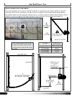
These overview diagrams show a power vent system as installed on a sample greenhouse. Note the positions of drive shaft
components and drive motor. Actual system may differ in size and components. Consult the diagrams for additional details.
See additional details on the following pages. Sample vent below may show components installed in different locations. Use the
diagrams on the previous pages and the pages that follow to correctly install the vent components for purchased vent.
B
A
Motor
B
Motor
(Vent Opened)
Panel Open Position
not to exceed 40°.
Vent rack is not shown.
Inside
Greenhouse
Support Post
Support Post Strut
A
Vent Rack Drive, Bearing Plate,
and Vent Rack—Vent Closed
B
Motor
(Vent Closed)
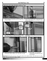
TOP of bottom
cross beam
CENTER of motor
drive sprocket
CENTER of motor
drive sprocket
to
OUTSIDE face of
support tube
6-3/4"
Vent Size
Bottom Cross
Beam-to-Drive Tube
36" Vent Panel
28-1/2"
48" Vent Panel
25-11/16"
60" Vent Panel
12-1/4"
For best results, position motor as close to
the center of the drive shaft as possible.
Do not mount drive motor at either end of
drive shaft.
See table above
for dimensions


