


AM-Jackal-2
more quick guides @ www.farmscanag.com/jackal
July 2013
13
Flow Meter (Wizard)
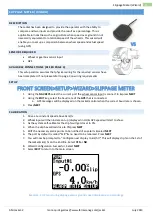
FLOW METER (WIZARD)
DESCRIPTION
The Jackal can be configured to monitor application rates of solid or
liquid products. If only one input is used the main screen will display the
flow information is L/min or Gal/min, or, if using the speed & area
function the Jackal can also display L/ha or Gal/Acre. At no stage can the
Jackal take into account multiple sections turning on an off and
adjusting the Ha/Ac to suit.
SENSORS REQUIRED
Flow Sensor ( 2 or 3 wire)
AVAILABLE CONNECTIONS (REFER PAGE 3)
This setup section assumes that physical wiring for the required sensors have been completed. If not please
refer to page 3 on wiring requirements.
SETUP
FRONT SCREEN>SETUP>WIZARD>FLOWMETER
1.
Using the
NAV KEYS
select the current port the flow sensor input is connected to & press
NEXT
2.
Press
EDIT
(to enable the port)
3.
Using the
EDIT KEY
select your unit of pulse for calibration
L (Litres) | GAL (gallons US)
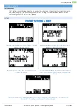
CALIBRATION
OPTION 1 : TARGET METHOD (AUTO CAL WITH A KNOWN VOLUME)
1.
Scroll down to
TARGET
and press
EDIT
2.
Enter a known volume to calibrate the flow meter against. I.e. 20L or
5Gal.
3.
Press
EXIT
4.
Start the pump, press
START
open the valve and pulses will now
accumulate.
5.
As SOON as the volume has been emptied press
STOP
6.
Press
CALC
, this will now enter the PPL/PPG factor into the Manual
Ratio
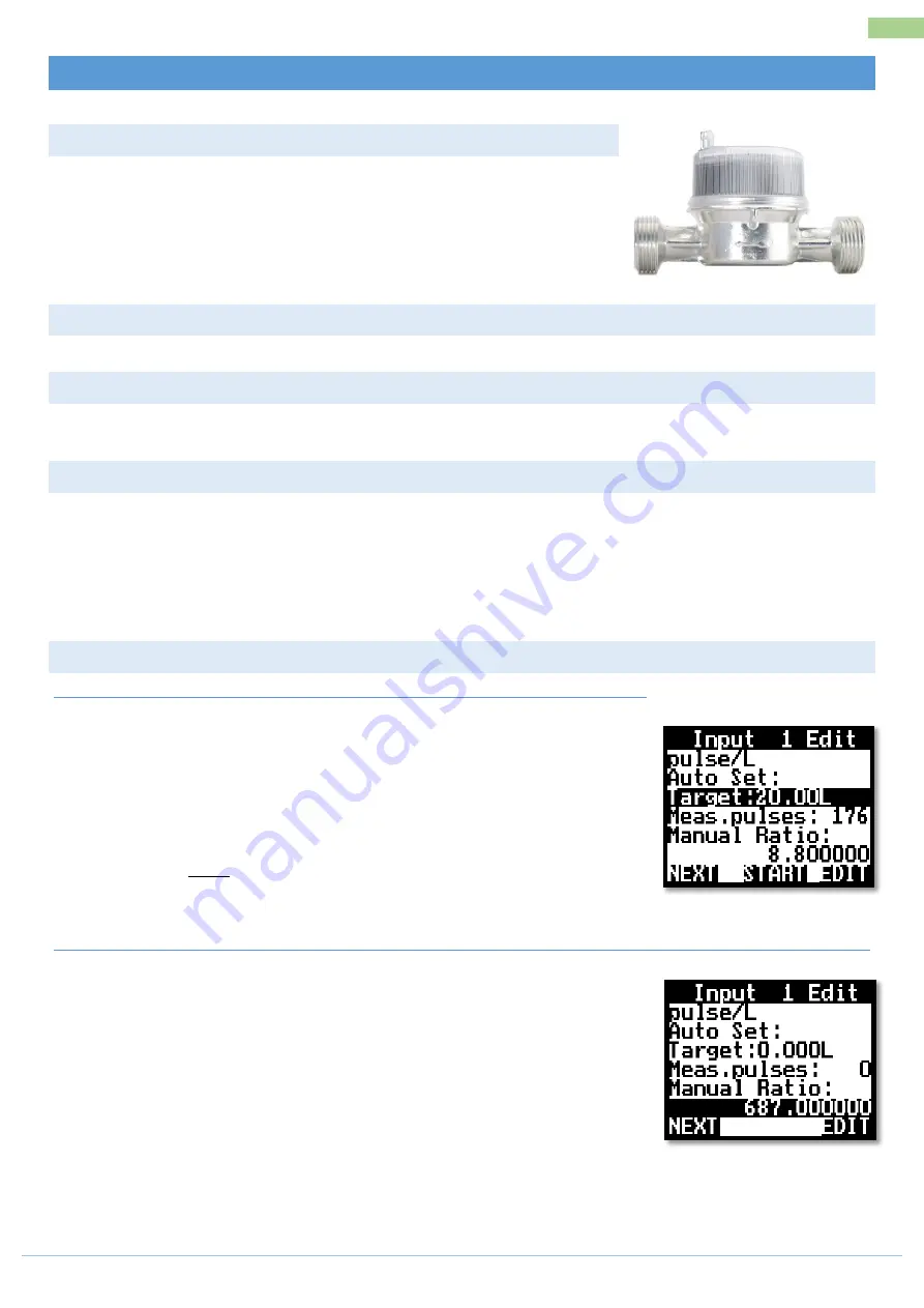
OPTION 2 : MANUAL RATIO (ENTER A KNOWN P PL/PPG FACTOR)
1.
Scroll down to Manual Ratio
2.
Press
EDIT
3.
Enter the known PPL/PPG factor as labelled on the flow meter
4.
Press
EXIT
5.
Press
NEXT
Summary of Contents for Jackal v2
Page 1: ......


