background image


Manual


SOFTER 12,5 PS 

20 

 54 

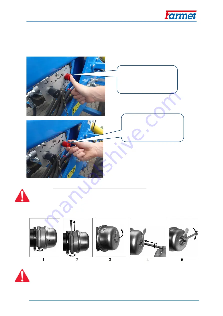
Description of the manual brake control when air ducting is connected 


The knob has to be pressed when travelling (there is no automatic change over). 


It does not need to be used when the machine is disconnected, the brake is automatically 
activated when the red quick coupling device of the tractor is disconnected. 


1.4.3.


Emergency brake release in case of air leak 


It is possible to release the brakes of the machine using special brake release bolts in case of a leak of air from 
the brake system. 


The bolts are included in the installation unit of the brake cylinder. 

Emergency brake release procedure in case of air leak 


Remove the bolts from the holders of the brake cylinder (Picture 1 and 2). 


Release the cap on the back side of the brake cylinder (Picture 3). 


Insert the bolt by its flat end (T-shape) into the opening in the cylinder and turn the bolt by 90° at the end of 
the opening so that the screw is arrested and cannot be pulled out (Pic. 4). 


Turn the nut (19 mm spanner) clockwise (Pic. 5). ATTENTION: Maximum torque is limited to 68Nm. 

PRESSED RED KNOB 

RELEASED BRAKES 

RELEASED RED KNOB 

APPLIED BRAKES 

Summary of Contents for SOFTER 12,5 PS

Page 1: ...l farmet farmet cz IČ 46504931 DIČ CZ46504931 Farmet a s Jiřinková 276 552 03 Česká Skalice CZ telefon 420 491 450 111 fax 420 491 450 136 GSM 420 774 715 738 OPERATING MANUAL SOFTER 12 5 PS Edition 5 effective from 8 10 2020 ...

Page 2: ...bilities of Use of the Disc Plough harrow The SOFTER disc plough harrow is intended for ploughing all types of soil up to the depth of 12cm 4 7 in Production label of the machine SOFTER 12 5 PS Table 1 Your Machine Characteristics MACHINE TYPE MACHINE SERIAL NUMBER SPECIAL DESIGN OR ACCESSORIES A Vehicle category according to R167 2013 B Approval number C Seventeen digit serial number VIN D Techni...

Page 3: ...king depth adjtustment 33 5 2 Washers on the drawbar 34 5 3 Setting the front equipment 34 5 4 Setting side deflectors 35 5 5 Setting edge discs 35 5 6 Setting shut off valve 36 5 7 Setting the rear flexible leveller 37 5 8 Setting the cutting disc 38 5 9 Turning at headland 38 6 ELECTRONIC HYDRAULIC CIRCUIT SWITCH 39 6 1 Description of the equipment 39 6 2 System wiring diagram 39 6 2 1 Designati...

Page 4: ...Manual SOFTER 12 5 PS 4 54 13 SERVICING AND WARANTY CONDITIONS 52 13 1 Servicing 52 13 2 WARRANTY 52 CE Certificate of Conformity 53 GB ...

Page 5: ...epth 3 5 12 cm 1 38 4 72 in Number of discs 510 mm 20in front 50 rear 51 Working performance 12 18 ha h 30 44 ac h Towing means 305 465 kW 410 625 HP Working speed 10 15 km h 6 9 5 mph Maximum transport speed 30 km h 18 6 mph Maximum slope grade 6 Tyre dimensions transport Tyre pressure 550 45 22 5 400 kPa Tyre dimensions tracing Tyre pressure 31x15 50 15 300 kPa Machine weight 13 000kg Recommende...

Page 6: ... persons when working with the machine or transporting the machine During machine work in the field or during transport the operator must control the machine from the tractor s cabin The operator may enter the machine structure only with the machine at rest and blocked against movement namely only for these reasons Adjustment of the machine working parts Repair and maintenance of the machine Relea...

Page 7: ...on the production label B 2 2 The dimensions of the transported machine including the transport means must comply with the valid regulations for road traffic decrees laws B 3 3 The transported machine must be always fastened to the transport means so that its spontaneous loosening could not happen B 4 4 The carrier is responsible for damage caused by the loosening of incorrectly or insufficiently ...

Page 8: ...ve their load capacity at least identical with the weight of the handled machine C 2 Machine fastening for handling may only be performed in places designed for that and marked with self adhesive labels showing the chain symbol C 3 After fastening suspending at designated points it is forbidden to move in the space of possible reach of the handled machine ...

Page 9: ... the operating manual Observe the instructions and safety regulations for machine operation during use P 1 H When connecting or disconnecting do not step between the tractor and the machine also do not enter this space if the tractor and the machine are not at rest and the engine is not turned off P 2 H Stay outside the reach of the tractor agricultural machine set if the tractor engine is in oper...

Page 10: ...e frames stay outside their reach P 50 H Secure the machine against unwanted movement P 52 H Do not approach the rotary parts of the machine if these are not at rest i e they do not turn P 53 H It is strictly folding and unfolding the side frames on slopes or inclined surfaces P 100 H The shown positions of the lever and the function of the hydraulic spherical valve located on the piston rod P 101...

Page 11: ...e hydraulic circuits and their functions 2 Folding and unfolding procedure 3 Valve control panel 4 Drawbar piston rod valve 5 Setting the drawbar washers according to the tractor hitch height 6 Transport axle wheels tracing wheels torque 7 Recommended tyre pressure for the transport axle tracing wheels ...

Page 12: ...icture 1 Location of safety labels on the machine SOFTER 12 5 PS P1H P2H P6H P37H P52H P13H P101H P100H P20H P50H P20H P50H P39H P53H P37H P53H P20H P50H P50H P52H P1H P37H P53H P37H P53H P42H P20H P50H P50H P20H 3 2 1 5 4 6 7 6 7 ...

Page 13: ...tation axle four side frames There are working discs in two rows on the central and side frames There are rollers in the rear that compact the loosened soil 1 1 WORKING PARTS OF THE MACHINE 1 Tractive pole with a folding leg 2 Supporting wheel 3 Front equipment 4 2 rows of discs 5 Roller 6 Transportation axle 7 Rear flexible leveller Picture 2 Work Parts of the Machine 4 Central frame Side frames ...

Page 14: ...y move suddenly when some of the valves are changed over Safety axle lock and folding Locking for transport The red folding and yellow axle circuits are closed The circuits cannot be moved Lever position on the left Used for transport Field work The red folding and yellow axle circuits are open Lever position on the right Used for work Attention The machine may move suddenly when changed over Cont...

Page 15: ...uit oil flow Setting the height of the lift is described in Chapter 5 6 Full lift Lifting the axle to the maximum height The stop valve is not activated Lever position on the left Used for transport and folding Accelerated short lift The stop valve is activated It restricts the height of the lift of the axle as set Lever position on the right Used at work to accelerate the turn at headland ...

Page 16: ...d Discs cannot be moved Discs must be maximally drawn in for folding The valve must be closed Used for transport and folding Unlocked discs The green circuit valve is open The working depth can be adjusted Used for work Shut off valve on the drawbar piston rod Used for closing the supply of pressure oil to the drawbar piston rod Prevents the machine from dropping when the hose breaks during transp...

Page 17: ...Side and edge frame folding Red circuit 2 Hooks to secure frames for transport Red circuit 3 Axle Yellow circuit 4 Setting the disc depth Green circuit 5 Front equipment Blue circuit 6 Drawbar piston rod Yellow circuit 7 Support leg White circuit 8 Tractor switchboards ...

Page 18: ...efore driving If the machine is equipped with brakes they must be connected to the tractor when driving Always release the brakes of the machine when lifting the machine on the axle ATTENTION The parking brake is activated automatically when there is a leak of air from the system and physical brake release is only possible mechanically see below 1 4 1 Brake distribution diagram 1 Quick coupler red...

Page 19: ...nnected When the air hoses are disconnected the parking brake is automatically activated To release the brakes for manipulation use the black knob The control is only functional when there is enough air in the air brake reservoir The system is automatically changed over to the travelling drawn out position when pressurized Released black knob The parking brake is applied Pressed black knob The par...

Page 20: ...e release bolts in case of a leak of air from the brake system The bolts are included in the installation unit of the brake cylinder Emergency brake release procedure in case of air leak Remove the bolts from the holders of the brake cylinder Picture 1 and 2 Release the cap on the back side of the brake cylinder Picture 3 Insert the bolt by its flat end T shape into the opening in the cylinder and...

Page 21: ...aintenance The circuits of the indicators include connected resistances KR KL for proper indication of the function in the tractor SYMBOL DESCRIPTION A 7 pin plug ISO 1724 LP Left front headlight PP Right front headlight KL Left controller KP Right controller LZ Left taillight PZ Right taillight Table 1 Connection of the 7 pin plug on the machine No SYMBOL FUNCTION 1 L Left indicator 2 54G Rear fo...

Page 22: ...ooks are properly locked before driving on roads When driving on roads the red circuit has to be closed with the valve Before unfolding release the hooks by changing them to the bottom end position Before folding check that the hooks are in the bottom position 1 7 TRANSPORT RESTS ON THE AXLE The transport rests on the axle are used as a safety component when driving on roads When the machine is lo...

Page 23: ...st be used whenever an unauthorized use of the machine is possible Picture 3 Device against unauthorized use 1 9 TOOL SET There is a box with a tool set and scraper placed on the drawbar The box contains wrenches from size 36 to 100 and a wrench adapter There are stickers on the box lid showing the folding and unfolding procedures The scraper is used for cleaning the machine before folding Scraper...

Page 24: ...sport safety and environmental protection The operator must check the machine before every use commissioning from the standpoint of completeness work safety work hygiene fire safety transport safety and environmental protection A machine showing signs of damage must not be commissioned Aggregation of the machine with the tractor is to be performed on a flat and hardened surface When working on slo...

Page 25: ...9 7 23 6 in Mechanism of the aggregation of the bottom fixed suspension Pin 50mm 1 96 in Pin 70mm 2 75 in Ball K80 Requirement for the tractor s hydraulic system Side frame folding circuit Circuit pressure 200 bar 2900Psi 2 pcs of quick coupler sockets ISO 12 5 Axle lifting circuit Circuit pressure 200 bar 2900Psi 2 pcs of quick coupler sockets ISO 12 5 Disc lifting circuit Circuit pressure 200 ba...

Page 26: ... frames folding 1 TAPE folding side frames into the transport position locking the folded side frames with hooks 2 TAPES unfolding side frames into the work position unlocking the side frame hooks YELLOW CIRCUIT lifting the machine into the transport position and when turning 1 TAPE lifting the machine on the axle and drawbar 2 TAPES lowering the machine on the axle and drawbar GREEN CIRCUIT contr...

Page 27: ... under gas pressure even after it has been emptied Empty the pressure vessel in case of any work on the hydraulics of the machine The manometer must not show any pressure or the pressure on the manometer must decrease to 0 bars Only then it is permitted to work on the hydraulic circuit It is prohibited to disassemble the parts of the machine hydraulic system that are pressurized Hydraulic oil that...

Page 28: ...s raised on the axle Check free turning and sufficient lubrication of the folding mechanism of edge frames before folding During folding or unfolding check the side frames and have them continuously fold into the end position to the stoppers Remove stuck soil from folding points soil may impair function and cause damage to the mechanics Soil may also apply excessive load on the machine frames duri...

Page 29: ...ers on the drawbar piston rod chapter 5 2 Tilt the end stops of the axle piston rods 2 Release the locking hooks downwards Unfold the machine set pressure in the circuit at 100 bar red circuit The machine is prepared for work Change the control lever of the shut off valve to the work position 3 Change the control lever of the shut off valve to the work position and open the valve for the green cir...

Page 30: ...le lever of the shut off valve to the transport position Close the green circuit of the discs Lift the machine to the maximum height yellow circuit Fold the machine using the red circuit The front equipment will automatically move to the minimum depth Lift the locking hooks 3 Add all the washers to the drawbar piston rod Insert the end stops of the axle piston rods Lower the machine onto the washe...

Page 31: ...Manual SOFTER 12 5 PS 31 54 CAUTION The machine must only be transported by the axle not rollers Picture 4 Transport of the machine ...

Page 32: ...ort on roads laws decrees after connecting the machine to the tractor for reason of a change of the axle load The driving properties of the set also change depending on the terrain nature adapt the manner of driving to these conditions Only machines with a valid technical certificate issued in accordance with the valid regulation on the approval of technical qualification and operation on public c...

Page 33: ...e depth when turning it is required to keep maximum pressure in the yellow circuit for about 2 seconds after the machine is lifted The arrow position may be adjusted by changing the length of the drawbar Picture 5 Working depth indicator Picture 11 Machine adjustment Tractive pole Setting the plain of the machine with washers Connecting drawbars of the front and rear row Adjustable edge discs sequ...

Page 34: ...ange when the working depth changes The colours of washers Picture 13 are indicative All washers must be inserted for transport The number of washers is stated on the sticker Picture 14 When transporting the machine on roads all the washers must be used and the machine must be lowered onto the washers to achieve a height below 4 metres Picture 6 Washers on the drawbar piston rod Grey setting by th...

Page 35: ... is shown on the piston rod indicator Picture 15 Position 4 highest labour intensity Position 1 deactivated The setting is independent of the disc working depth setting There are flow limiters in the circuit It may be deactivated when there is a large quantity of crop residue marked position 1 An excessive down pressure on the front cutting roller may worsen recessing of the discs Picture 8 Front ...

Page 36: ...or is set longitudinally 5 5 SETTING EDGE DISCS The edge discs on both sides of the machine have an adjustable position and they can be recessed differently to the other discs The adjustment is executed so that the working depth of the edge discs is lower approx of the depth of the other discs Proper setting is important for the sequence of travel without any unevenness The setting may be changed ...

Page 37: ...of the other holes Picture 18 The recommended setting is when the central roller is about 5 cm above ground during the turn To lift the machine to the maximum height for transport it is required to change the control lever on the drawbar to the transport position Moving the adjustable links down increases the lifting height using the holes in position 1 instead of position 3 Attention When the lif...

Page 38: ... need to be changed according to the work conditions It is changed by changing the position of the pins in the setting link It may be deactivated when getting clogged Picture 11 Picture 11 Deactivation of the rear flexible leveller Picture 10 Setting the rear flexible leveller Rear flexible leveller Setting link Increasing labour intensity Reducing labour intensity ...

Page 39: ...bout 2 seconds piston rod restart It consolidates the positions of the piston rods of all frames at maximum depth Use the yellow circuit to put machine back into the working position draw the piston rods of the transport axle into the limit position a Turn with the shut off valve Set the shut off valve lever to the correct position according to Chapter 1 2 The axle will lift to the set height the ...

Page 40: ...educing the final number of connected hydraulic circuits between the tractor and the machine 6 2 SYSTEM WIRING DIAGRAM 6 2 1 Designation of system components 1 Output 1 CIRCUIT 1 CONTROL 2 Output 2 CIRCUIT 2 CONTROL 3 Output 3 CIRCUIT 3 CONTROL 4 Electrohydraulic valve of CIRCUIT 1 5 Electrohydraulic valve of CIRCUIT 2 6 Electrohydraulic valve of CIRCUIT 3 7 Ball valve 8 Tractor quick couplers 9 C...

Page 41: ...Manual SOFTER 12 5 PS 41 54 6 2 2 Wiring diagram ...

Page 42: ...OFF controller switch Control button of the activated circuit Pictogram of the activated circuit Controlled circuit LED indicator Supply line from tractor 12V Control line to the block on machine Hydraulic outputs of the switchboard Hydraulic input of the switchboard Electrohydraulic valve cover ...

Page 43: ...Never replace the fuse with a different value 6 4 FUNCTIONS PICTOGRAMS POWER button Activates the power supply of the control device and launches the system It is indicated by the red diode when activated Circuit selection buttons The individual circuits are selected using the control buttons of the individual circuits Each button has a pictogram assigned to identify the controlled circuit Only on...

Page 44: ...th a reversed switching function Manual emergency control The switchboard may be controlled mechanically in emergency The control is performed by manually pressing the gate valve of the switchboard via the spring e g using a suitable bar with a diameter of about 3 mm The switchboard cover has holes on the bottom side for this case Example Frame Folding circuit control Close this circuit by pressin...

Page 45: ...ively stretched and that they cannot be caught by the tractor shoulders 7 2 DEPTH CONNECTING RODS FOR THE FRONT ROW The working depth is set at the rear row of discs The front row is connected to its using an adjustable connecting rod The setting does not have to be adjusted in regular conditions With correct factory settings the distance between the lug and the lock nut is 40 mm Picture 23 With c...

Page 46: ...etting may have to be adjusted according to the conditions The setting must correspond to the number of washers on the drawbar and the tractor hitch height 7 4 ROLLER POSITIONS The roller bearings may be mounted in different positions on the side plates The factory setting is set at the central position position 2 The setting does not usually need to be changed 1 2 3 4 Picture 15 Setting the traci...

Page 47: ... PS 47 54 7 5 AIR JET DRAINAGE Drain the air jet regularly once a week according to the maintenance plan Drain water without any air pressure in the air jet Excessive water amount may corrode the brake system Drain valve ...

Page 48: ...t marked points or at points suitable for that During adjustment cleaning maintenance and repair of the machine you must secure those parts of the machine that could endanger the operator by falling or another movement For catching the machine during handling using lifting equipment use only the places marked with self adhesive labels with the chain sign Upon a failure or damage of the machine imm...

Page 49: ...draulic rollers bearings electric and electronic parts The seals and bearings are not waterproof at high pressure Hydraulic system Checking the function tightness mounting and worn spots of all hydraulic parts and hoses X X Hydraulic hoses replacement Damaged external casing of the hose mechanically or blistered Fluid seepage especially the end piece Bumps or blisters on the hose Deformed or corro...

Page 50: ...time after 10 hours of operation Wheel replacement after 10 hours of operation M 22 x 1 5 440 Nm M 20 x 1 5 340 Nm X 100 h Brake system Brake line and hoses check the function tightness mounting and clamping or breaking X X X Brake components check the function tightness mounting X X X Air nozzle drain using the draining valve X X Draining valve check the function clean and replace sealing X X Pip...

Page 51: ... machine do not spray oil or similar agents on the plastic parts Store the machine away with piston rods draws in if possible Spray the piston rods of the hydraulic cylinders with suitable anti corrosion agents Check the tightness of all bolt and plug in connections see the torque chart Check for any damage of the electric cables and replace if needed Brake system Preserve the anti freeze fluid fo...

Page 52: ...ne against spontaneous movement using scotches or another suitable tool When storing lower the machine into the lower position using hydraulics The machine must not lean on the discs as the working discs of the machine could be damaged Secure the machine against access of unauthorised persons 10 MACHINE LUBRICATION SCHEDULE All the lubrication points should also be lubricated at the beginning and ...

Page 53: ... for these machine parts main frame axle and machine tow bar For other parts of the machine the manufacturer provides a warranty of 12 months The warranty is provided from the date of sale of the new machine to the end user consumer 13 2 2 The warranty applies to hidden defects that will show in the warranty period with proper use of the machine and while fulfilling the conditions stated in the op...

Page 54: ...iknummer n de production заводской номер numer produkcyjny 3 Příslušná nařízení vlády č 176 2008 Sb směrnice 2006 42 ES Applicable Governmental Decrees and Orders No 176 2008 Sb Directive 2006 42 ES Einschlägige Regierungsverordnungen NV Nr 176 2008 Slg Richtlinie 2006 42 ES Décrets respectifs du gouvernement n 176 2008 du Code directive 2006 42 CE Соответствующие постановления правительства 176 2...

Reviews: