Manual
FANTOM 850 PS
12
│
33
1.1.5
Central frame
Boční rámy
1.1.1
1.1.4
1.1.3
1.1.7
Side frame
1.1.2
1.1.6
1.
DESCRIPTION
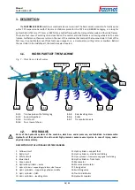
The
FANTOM FX 850 PS
machine is constructed as semi-carried.
The basic version consists of a tractive pole
with a TPS suspension bar with
36 mm or
60 mm pivots for the TPS 3 and KIROVEC category,
or a loop for
bottom hitch
(
51 mm,
71 mm
or K80 hitch),
a central frame with the transportation axle and four side frames.
There are four rows of working shares located on the central and side frames
and tracing wheels on the side
frames. Furthermore, there are rollers in the rear of the machine that compact the loosened soil. In front of the
first row, it is possible to mount front tools upon request, i.e. a crossboard, a cutting roller, or coulters. Behind
the rear roller in the middle part, the machine axle is located.
1.1.
WORK PARTS OF THE MACHINE
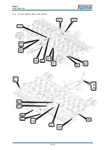
Fig. 2 – Work Parts of the Machine
1.1.1
Tractive pole with a folding leg
1.1.2
Supporting wheel
1.1.3
Front tools
1.1.4
Four rows of shares
1.1.5
Rear levelling discs
1.1.6
Roller
1.1.7
Transportation axle
1.2.
HYDRAULICS
Parts of the hydraulic system of the machine, which are under pressure, are forbidden to disassemble.
Hydraulic oil that penetrates the skin under high pressure causes severe injuries. In case of injury, seek a
physician immediately.
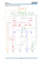
DESCRIPTION OF THE HYDRAULIC SYSTEM DIAGRAM
1.
Yellow circuit
2.
Red circuit
3.
White circuit
4.
Blue circuit
5.
Green circuit
6.
Hydraulic cylinders – axles
7.
Hydr. cylinders – supporting cylinders, side frames
8.
Hydr. cylinders – supporting cylinder, middle
9.
Hydr. cylinder – hitch
10.
Hydr. cylinders – levelling discs
11.
Hydr. cylinder – support foot
12.
Hydr. cylinders – side frame folding
13.
Hydr. cylinders – frame securing against unfolding
14.
Hydr. cylinders – front tools
15.
Manometer
16.
Pressure accumulator
17.
Closing valve
18.
Switching valve
19.
Tractor distributor
20.
Hydraulic couplers


