


Maintenance - BW150
38
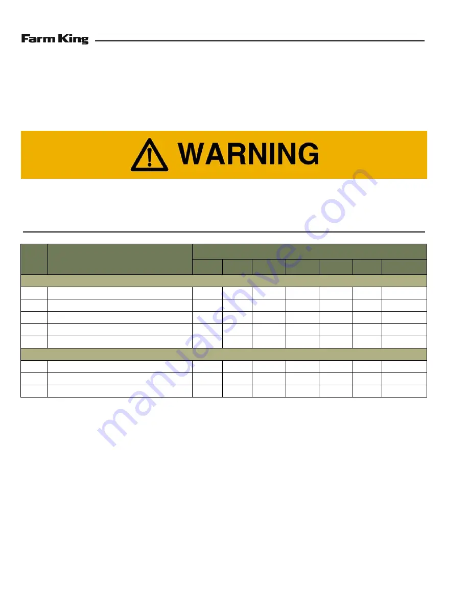
SERVICE SCHEDULE
Maintenance Intervals
Maintenance work must be done at regular intervals. Failure to do so will result in excessive wear and early failures.
The service schedule is a guide for correct maintenance of the Bale Wrapper.
#
DESCRIPTION
SERVICE PROCEDURES
Check
Clean
Lube
Change
Adjust
Drain
Locations
Daily Maintenance (or every 8 hours)
1
Tire Pressure
•
2
Wheel Bolts
•
3
Hydraulic Hoses And Connections
•
•
4
Rotary Frame Drive Chain
•
•
5
Rotary Drum Drive Chains
•
•
Weekly (or every 50 hours)
6
Hydraulic Hoses And Connections
•
7
Check All Hardware And Safety Devices.
•
8
Bale Wrapper Condition
•
•
Instructions are necessary before operating or servicing equipment. Read and understand the
Operator and Parts Manual and safety signs (decals) on equipment. Follow warnings and instructions
in the manuals when making repairs, adjustments or servicing. Check for correct function after
adjustments, repairs or service. Untrained operators and failure to follow instructions can cause
injury or death.
Summary of Contents for BW150
Page 2: ......
Page 4: ...Table of Contents BW150 4 ...
Page 6: ...Warranty Registration BW150 6 ...
Page 8: ...Introduction BW150 8 ...
Page 12: ...Safety BW150 12 ...
Page 20: ...Safety BW150 20 ...
Page 22: ...Operation BW150 22 ...
Page 34: ...Operation BW150 34 ...
Page 36: ...Maintenance BW150 36 ...
Page 42: ...Maintenance BW150 42 ...
Page 44: ...Parts Identification BW150 44 ...
Page 60: ...Parts BW150 60 ...
Page 62: ...Specifications BW150 62 ...
Page 67: ...Warranty BW150 67 WARRANTY WARRANTY 71 ...
Page 68: ...Warranty BW150 68 ...
Page 72: ...Alphabetical Index BW150 72 ...
Page 73: ......


