background image

P/N 315-049708FA-4

6

1.

Remove the cover from the housing.

2. Loosen the screw and rotate the tube retainer until the

input tube is inserted and oriented properly. Ensure that
the notched end of the tube is inside the housing and
that the air input sampling tube is positioned so that the
input holes are directly facing the airflow.

3. Once the tube is installed, rotate the retainer back into

place and tighten screw.

4. Install the outlet tube in the remaining position. Once

the tube is installed, rotate the retainer back into place
and tighten screw.

Mounting

After securing the input and outlet tubes to the duct smoke
unit, (or initially placing the tubes through the 1¼” holes
drilled or punched in the HVAC duct to accept the input and
outlet tubes and then attaching them to the duct unit), hold
the duct unit assembly in position and use (2) # 12 X 

3

/

4

sheet metal screws (packaged in the installation kit) to secure
the duct smoke detector to the HVAC duct sheet metal.

Air Duct Sampling Tube Pressure Measurement

The Model 8883 Pressure Differential Measuring device
should be used to ensure that the sampling tube pressure
differential is within the specified limits. The differential
pressure between the two tubes should be greater than 0.01
inches of water and less than 1.2 inches of water. Qualified
personnel should take measurements in accordance with
the 8883 instructions, P/N 315-085535FA.

WIRING

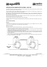
Conduit Knockouts To remove plastic knockout, first cut the plastic tab on the

specific knockout. Refer to Figure 4 to locate the tab.  Then,
using a screw driver placed at the tab location, tap with a
hammer until the knockout breaks out. Clean the hole before
installing conduit.

PLASTIC TAB

KNOCKOUT

SIDE REAR OF AIR DUCT HOUSING

KNOCKOUT FACTORY
REMOVED

Figure 4

Removing the Knockouts

Summary of Contents for 8742

Page 1: ...c see char har har har harts on the page ts on the page ts on the page ts on the page ts on the page 1 1 1 1 12 of this manual 2 of this manual 2 of this manual 2 of this manual 2 of this manual TECHN...

Page 2: ...detector is equipped with cover removal switch SW1 that instantly provides a trouble condition upon removal of the clear cover For all testing and inspection with the cover removed the cover removal...

Page 3: ...R PLENUM FRESH AIR INTAKE DAMPER D D Figure 1 Typical Mounting of Duct Housing OUTLET TUBE INPUT SAMPLING TUBE CENTER LINE OF DUCT C L MOUNTINGTHE AIR DUCT HOUSING Location on Duct System This guideli...

Page 4: ...m of filters fires occurring in the filters will be detected but if the filters become blocked insufficient air flow through the duct unit will prevent the correct operation of the duct detector Duct...

Page 5: ...be cut to length and must span at least 80 the width of the duct Sampling tubes over 3 0 must be supported on the opposite side of the duct To ensure the correct operation the red stopper stopper in i...

Page 6: ...d the duct unit assembly in position and use 2 12 X 3 4 sheet metal screws packaged in the installation kit to secure the duct smoke detector to the HVAC duct sheet metal Air Duct Sampling Tube Pressu...

Page 7: ...e loop Note any limitations on the number of detectors and restrictions on the use of remote devices permitted for each circuit When replacing a detector with a different model be aware that existing...

Page 8: ...the initiating circuit 3 Do not use looped wire under base terminal 4 Break wire run to provide supervision of connection 5 The green grounding screw in the wiring compartment of the air duct housing...

Page 9: ...6 or 5 TB3 5 or 6 TB1 1A TB1 TB1 TB1 MODEL 8741 MODEL 8743 MODEL 8743 8710 8713 OPTIONAL REMOTE ALARM INDICATOR MODEL 8727C OR 8727W SEE NOTE 2 LOOP WIRES SEE COMPATIBLE CONTROL EQUIPMENT TABLE 8710 8...

Page 10: ...zle model AD TGN purchased separately available from Siemens Industry Inc insert the test gas nozzle into the hole in the red test plug in the unit cover Press can against cover for about 1 2 second t...

Page 11: ...F ed Farada arada arada arada araday S y S y S y S y Service R ervice R ervice R ervice R ervice Represent epresent epresent epresent epresentat at at at ati i i i ive ve ve ve ve If the fire alarm sy...

Page 12: ...P M 0 0 0 6 C P M 5 A F 0 5 8 4 3 0 5 1 3 N P 1 0 4 W L 3 A F 7 9 9 5 9 0 5 1 3 N P 1 0 4 W L A 4 E Z W L 4 A F 8 1 0 6 9 0 5 1 3 N P 1 0 4 W L A 8 E Z W L 3 A F 2 2 0 6 9 0 5 1 3 N P R O T C E T E D...

Reviews: