


15
GB
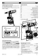
KJ 45
KJ 45
Revision - 04
Date 10-2008
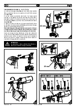
f3
Tie rod min. stroke
Revolutions (M)
~ 2 mm
0
Tie rod stroke
Revolutions (M)
~ 0.4 mm
1
Tie rod max. stroke
Revolutions (M)
~ 8 mm
15
+
-
0
1
2
3
4
5
6
7
9
8
10
11
12
13
14
15
M12
1 ÷ 4
M4
0.3
÷ 4
M5
0.5 ÷ 5
M8
0.8 ÷ 6
M10
1 ÷ 6
M12
1 ÷ 7
/
M6
0.5 ÷ 6
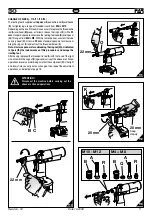
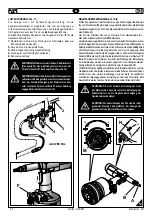
PLACING OF THE INSERT
(fi g.
f4-f5-f6
)
Check that the threaded tie rod (
A
) and head (
B
) couple assembled on
the riveting tool is suitable to the size of the insert to be used.
Adjust the stroke as indicated (fi g.
f2-f3
).
Introduce the insert on the tie rod (
A
) and push slightly on it as indicated
in fi gure
f4
, so as to make it clamp automatically on the threaded tie
rod. Make sure that the insert head touches the head (
B
) checking
that the tie rod (
A
) comes out of
2mm
from the insert.
In case of further adjustments of the tie rod (
A
) follow the instructions
of page 18.
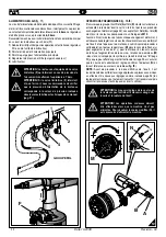
It is possible to place the insert pushing the button (
D
) and keeping it
pushed up to the complete release of the tie rod (fi g.
f5
).
For a correct placing and right working of the machine, the inserts to
be used should be properly cleaned.
Note:
According to the desired clamping, carry out other adjustments
of the riveting tool stroke, rotating the knob (
M
) (fi g.
f2-f3-f6
), if
necessary.
Insuffi cient deformation =
the insert could rotate inside the housing
compromising its use and resistance.
Excessive deformation =
possible damages of the insert and tie rod
(
A
) with eventual breaks of both components.
D
M
f5
f4
~2mm
A
B
f6
Summary of Contents for KJ45
Page 79: ......


