


8
4.
Grasp the flats on lock collet [64] with needle nose pliers between lower spring
coils. Holding the dial [60] turn it, torsion shaft, and collet [65] counterclockwise to
tighten the thin notched portion of lock collet [64] against spring [67]. and collet 67-
3].
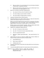
C.
Mounting Torsion Shaft Assembly in the Calibration Fixture.
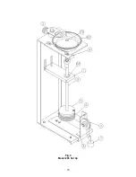
Re-assemble the Calibration Fixture and set it up for the Model 280 torsion shaft
assembly.
(Refer to Fig. 2).
1.
Install the pulley [3] into the top hole of the Pulley Support Bracket.
2.
Loosen the two screws holding the lower bearing support bar, [1] and position it at
the top of the slots for the 280 Rheometer and re-tighten the screws.
3.
Slide torsion shaft assembly into fixture from the top. Position torsion body hub into
the hole in the top of the fixture and bearing [68] in the hole in the lower bearing
support bar [1]. Rotate the torsion body to align the flat of the torsion body cross
wise of the fixture. Secure the torsion assembly into the fixture by locking the lock
bar [4] over the flat of the torsion body.
4.
Remount the Dial [60] onto the top of the torsion shaft [66] with screw [79].
5.
Position the hairline/magnifier [2] in the lower groove of its support. Rotate the
hairline/magnifier [2] so the hairline aligns with the divisions on the dial and lock in
place. Loosen set screw [81-B] to loosen collet [67-2] in the torsion body [61], then
rotate the dial and bob shaft to align Zero with the hairline. Lock collet [67-2] in this
position with set screw [81-B].
6.
Screw Calibration spool [5] onto bob shaft, threads down, until it is tight. Wind two
to three turns of thread around the drum clockwise as viewed from the top of the
spool. (Refer to Fig. 2.) Route the thread over the sheave, and allow it to hang.
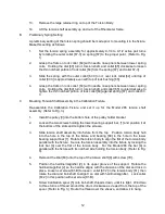
D.
Taking the Readings
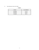
Hang the 25, 50 and 75 Gram weights each in turn on the loop in the end if the thread and
note the dial readings obtained. (Refer to Table 1). If the dial readings are higher than
shown in Table 1 - shorten the active part of the spring. If the dial readings are lower than
shown in Table 1 - lengthen the active part of the spring.
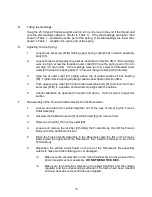
E.
Adjusting Torsion Spring:
1.
Loosen hex set screw [81-B] holding upper spring collet [67-2] in torsion assembly
body [61].
2.
Loosen torsion spring adjusting collet as described in Section 3B-2. If the readings
were too high, screw the threaded outer collet [67-3] up the spring pairs (1/4 turn
will drop 3-5 dial units). If the readings were too low, screw the threaded outer
collet [67-3] down the spring pairs (1/4 turn will change reading 3-5 dial units).
3.
Align top of outer collet [67] slightly above top of widest section of lock bushing
[65]. Tighten torsion spring adjusting collet as described in Section 3B-4.
Summary of Contents for 280
Page 5: ...2 ...
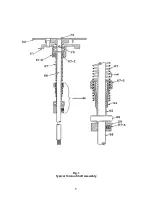
Page 8: ...5 Fig 1 Typical Torsion Shaft Assembly ...
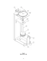
Page 9: ...6 Fig 2 Model 280 Set Up ...
Page 13: ...10 Fig 3 Model 286 Set Up ...


