background image

5

Ceiling fan performance and energy savings rely 
heavily on the proper installation and use of the 
ceiling fan. Here are a few tips to ensure efficient 
product performance.
   

Using the Ceiling Fan Year Round

Summer Season: 

Use the ceiling fan in the clockwise

direction. The airflow produced by the ceiling fan 
creates a wind-chill effect, making you “feel” cooler. 
Select a fan speed that provides a comfortable breeze, 
lower speeds consume less energy.

Winter Season: 

Reverse the motor and operate the

ceiling fan at low speed in the counterclockwise 
direction. This produces a gentle updraft, which forces 
warm air near the ceiling down into the occupied 
space. Remember to adjust your thermostat when 
using your ceiling fan-additional energy and dollar 
savings could be realized with this simple step!

Choosing the Appropriate Mounting Location

Ceiling fans should be installed, or mounted, in the middle 
of the room and at least 10 feet from floor to the blade and 
18 inches from wall to the blade. If ceiling height allows, 
install the fan 11-12 feet from floor to the blade for optimal 
airflow. Consult your Fanimation Retailer for optional 
mounting accessories.


Turn Off When Not in the Room

Ceiling fans cool people, not rooms. If the room is 
unoccupied, turn off the ceiling fan to save energy.


Your new ceiling fan will require a grounded electrical 
supply line of 120 volts AC, 60 HZ, 15 Amp Circuit. 
Electrical code requires use of a fan-rated outlet box to 
support the extra weight and motion associated with a 
ceiling fan. A fan-rated box will be labeled as such and 
typically supports up to a 70lbs ceiling fan. Fan-Rated 
Outlet Boxes vary in ratings and design. Ensure the 
ratings of your ceiling fan outlet box meet the 
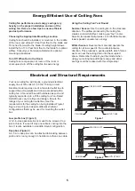
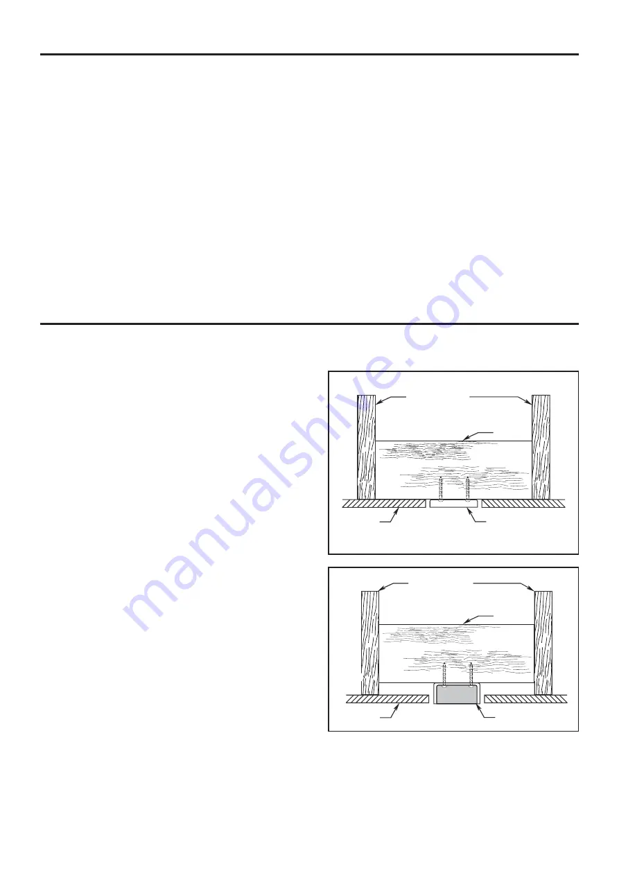
requirements for the ceiling fan being installed. Figure 1, 
Figure 2 and Figure 3 depicts different structural  
configurations that may be used for mounting the outlet 
box.

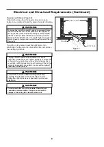
Low profile box (Figure 1)

A 1/2-in.-deep pancake box is meant to be screwed to a 
joist or block. It’s used if only one cable is coming into the 
box. It is also available in a saddle-mount configuration.   

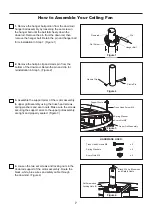
Deep box (Figure 2)

A 2-1/4-in.-deep box can be attached to blocking between 
joists and is roomy enough to handle more than one cable.  
 

CEILING JOIST

CEILING

OUTLET BOX

Figure 1

Figure 2

CEILING JOIST

2" x 4"

2" x 4"

CEILING

OUTLET BOX

Energy Efficient Use of Ceiling Fans

Electrical and Structural Requirements

Summary of Contents for KLOUT FP3070 Series

Page 1: ...urchase Date ATTACH YOUR RECEIPT HERE AND REGISTER YOUR FAN AT FANIMATION COM READ AND SAVE THESE INSTRUCTIONS Net Weight 17 88 lbs 8 11 kgs KLOUT CEILING FAN MODEL FP3070 Espa ol p 20 For best and qu...

Page 2: ...to an ungrounded conductor power supply If the conductor of a fan is identified for equipment grounding then it should be connected to an equipment grounding conductor WARNING TO REDUCE THE RISK OF E...

Page 3: ...the fan or Fanimation 7 Fanimation reserves the right to modify or discontinue any product at any time and may substitute any part under this warranty 8 Under no circumstances may a fan be returned wi...

Page 4: ...ll or use fan if any part is damaged or missing This product is designed to use only those parts supplied with this product and or any accessories designated specifically for use with this product by...

Page 5: ...your Fanimation Retailer for optional mounting accessories Turn Off When Not in the Room Ceiling fans cool people not rooms If the room is unoccupied turn off the ceiling fan to save energy Your new...

Page 6: ...re or shock follow all wiring instructions carefully Any electrical work not described in these instructions should be done or approved by a licensed electrician Figure 3 CEILING JOIST CEILING OUTLET...

Page 7: ...the ball falls freely down the downrod Remove the pin from the downrod then remove the hanger ball Retain the pin and hanger ball for reinstallation in Step 7 Figure 1 Figure 1 Downrod Hanger Ball Set...

Page 8: ...ceiling canopy Figure 6 CAUTION All set screws must be checked and retightened where necessary before installation Figure 8 Figure 9 Hanger Bracket 9 Remove one of the two shoulder screws in the hange...

Page 9: ...olt and flat washer attach safety cable to ceiling joist or wood structural member The lag bolt will pass through the flat washer safety cable loop and into the building structure Figure 3 NOTE Ceilin...

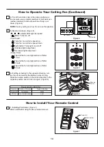
Page 10: ...t a licensed electrician for advice as it must be grounded for safe operation CAUTION INCORRECT WIRE CONNECTION WILL DAMAGE THIS RECEIVER 1 To set the code on receiver unit slide dip switches to the s...

Page 11: ...cluding ground and that no bare wire is visible at the wire connectors except for the ground wire Do not operate fan until the blades are in place Noise and motor damage could result 4 After connectio...

Page 12: ...or assembly shaft and secure with hairpin clip and blade holder trim cover Figure 1 How to Assemble Your Fan Blade and Light Bulbs CAUTION Do not connect fan blade until the fan is completely installe...

Page 13: ...e that all connections are tight including ground and that no bare wire is visible at the wire connectors except for the ground wire Do not operate fan until the blades are in place Noise and fan dama...

Page 14: ...igure 6 Reverse Switch 4 To set the remote code in the same positions as the receiver use a small screwdriver or ball point pen neither included to slide dip switches firmly up or down Figure 4 NOTE F...

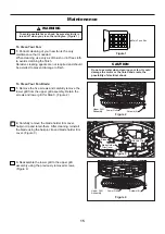
Page 15: ...not required and should be avoided to prevent damage to finish To Clean Your Fan To Clean Your Fan Blade Figure 2 1 Remove the five screws and carefully remove the lower grill from the upper grill ass...

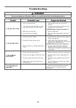
Page 16: ...1 Fuse or circuit breaker blown 2 Loose power line connections to the fan or loose switch wire connections in the switch housing 3 Dead battery in remote control 4 Make sure reverse switch position is...

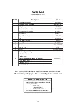
Page 17: ...70 10 11 7 8 Hardware Bags Containing Upper Grill Mounting Hardware Bags Containing 12 Wire Connectors 4 Safety Cable Kit Truss Head Screws M4 6 Spring Washers 6 Acorn Nuts M4 6 Insert FINISH CODES Re...

Page 18: ...llustration shown is not to scale or its actual configuration may vary Product parts are subject to change without notice Klout TM Model FP3070 Exploded View Illustration 14 11 1 2 3 4 5 6 7 8 9 10 12...

Page 19: ...10983 Bennett Parkway Zionsville IN 46077 Phone 888 567 2055 Outside U S 317 733 4113 FAX 866 482 5215 FANIMATION COM 2021 02 V 01 Copyright 2021 Fanimation...

Page 20: ...DJUNTE SU RECIBO AQU Y REGISTRE SU VENTILADOR EN FANIMATION COM LEA Y GUARDE ESTAS INSTRUCCIONES C digo de fecha Fecha de compra Para ofrecer un servicio r pido y de calidad por favor suministre el c...

Page 21: ...est n indicados para su uso con este producto podr a sufrir lesiones personales o da ar el ventilador ADVERTENCIA Para reducir el riesgo de lesiones personales no doble los soportes de las aspas borde...

Page 22: ...garant a expresa o impl cita Por la presente Fanimation niega todas las garant as impl citas que incluyen entre otras la comerciabilidad y la aptitud para determinado fin hasta donde la ley lo permita...

Page 23: ...ommag es Instrucciones para el desempaque Para su comodidad marque cada uno de los pasos A medida que completa cada paso coloque una marca de verificaci n Con esto se asegurar de completar todos los p...

Page 24: ...para un flujo de aire ptimo Consulte en su tienda minorista de Fanimation para obtener accesorios de montaje opcionales Apague el ventilador cuando no se encuentre en la habitaci n Los ventiladores s...

Page 25: ...A fin de evitar incendios o descargas el ctricas siga con cuidado todas las instrucciones de instalaci n el ctrica Cualquier trabajo el ctrico que no se describa en estas instrucciones deber ser real...

Page 26: ...de la bola colgante varilla aflojando el tornillo de presi n de la bola colgante hasta que la bola se libere de la varilla Retire el pasador del barral y luego extraiga la semiesfera Conserve el pasad...

Page 27: ...a a colocar la semiesfera en el barral como se indica a continuaci n Pase los cables de negro blanco azul cables y cable de soporte para techo a trav s de la semiesfera Pase el pasador a trav s de los...

Page 28: ...ventilateur afin d viter tout risque d lectrocution Figure 1 ADVERTENCIA La caja de distribuci n el ctrica de be estar bien asegurada y debe ser capaz de soportar una carga de al menos 15 9kg 35lb El...

Page 29: ...do que m s tarde se pueda realizar la instalaci n el ctrica 5 Fije el cable de seguridad al cable de soporte para techo Deslice la abrazadera de cables por el cable de seguridad del ventilador Pase el...

Page 30: ...n a tierra para un funcionamiento seguro PRECAUCI N UNA CONEXI N INCORRECTA DEL CABLE PODR A DA AR ESTE RECEPTOR ATTENTION UNE CONNEXION DE FIL INCORRECTE PEUT ENDOMMAGER CE RECEPTEUR ADVERTENCIA Par...

Page 31: ...cado TO MOTOR L al conductor negro del ventilador con el conector de cables que se adjunta con la unidad receptora Finalmente conecte el conductor azul de la unidad receptora al conductor azul de la i...

Page 32: ...el ctrica necesaria C mo instalar la carcasa de la cubierta 1 Instale la cubierta rotando la ranura clave en la cubierta sobre el tornillo de hombro del soporte del gancho teniendo cuidado de no pill...

Page 33: ...avec les pales assembl es peut endommager les pales du ventilateur ADVERTENCIA Para reducir el riesgo de lesiones personales no doble los soportes de aspas al instalarlos balancear las aspas o limpia...

Page 34: ...tores de cables con la excepci n del cable de toma de tierra No utilice el ventilador hasta que las palas est n colocadas en su lugar ya que de lo contrario se podr a causar ruido y da os 4 Para confi...

Page 35: ...hacia otros mandos a distancia modifique el c digo de combinaci n de su transmisor y receptor Luz LED del indicador Velocidad del ventilador Bot n Apaga el ventilador Velocidad del ventilado Enciende...

Page 36: ...bo la limpieza use s lo un cepillo suave o un pa o sin pelusas para evitar rayar el acabado No se requieren agentes abrasivos de limpieza los mismos deben evitarse para prevenir da os en el acabado Pa...

Page 37: ...4 Aseg rese de que el conmutador inversor est completamente a un lado 4 El conmutador inversor se encuentra en posici n neutra 2 Aseg rese de que los conectores de cables en la caja del interruptor n...

Page 38: ...del barral de la semiesfera Unidad del soporte de suspensi n Aspa Cubierta de ajuste de la soporte del aspa Rejilla inferior Mano a distancia LED Bombilla Receptor Bolsa de accesorios que contiene Con...

Page 39: ...Klout TM Modelo FP3070 Ilustraci n del despiece NOTA La ilustraci n que se muestra no est hecha a escala y su c guraci n real y o terminaci n puede variar 14 11 1 2 3 4 5 6 7 8 9 10 12 14 13 39...

Page 40: ...Copyright 2021 Fanimation Visite nuestro sitio Web en www fanimation com 10983 Bennett Parkway Zionsville IN 46077 Llame sin cargo al 888 567 2055 FAX 866 482 5215 Desde fuera de los EE UU llame al 3...

Reviews: