-3-
A
Photography lights will be installed in the camera or
photographic camera lights before removed, is required to set
the power switch in OFF.
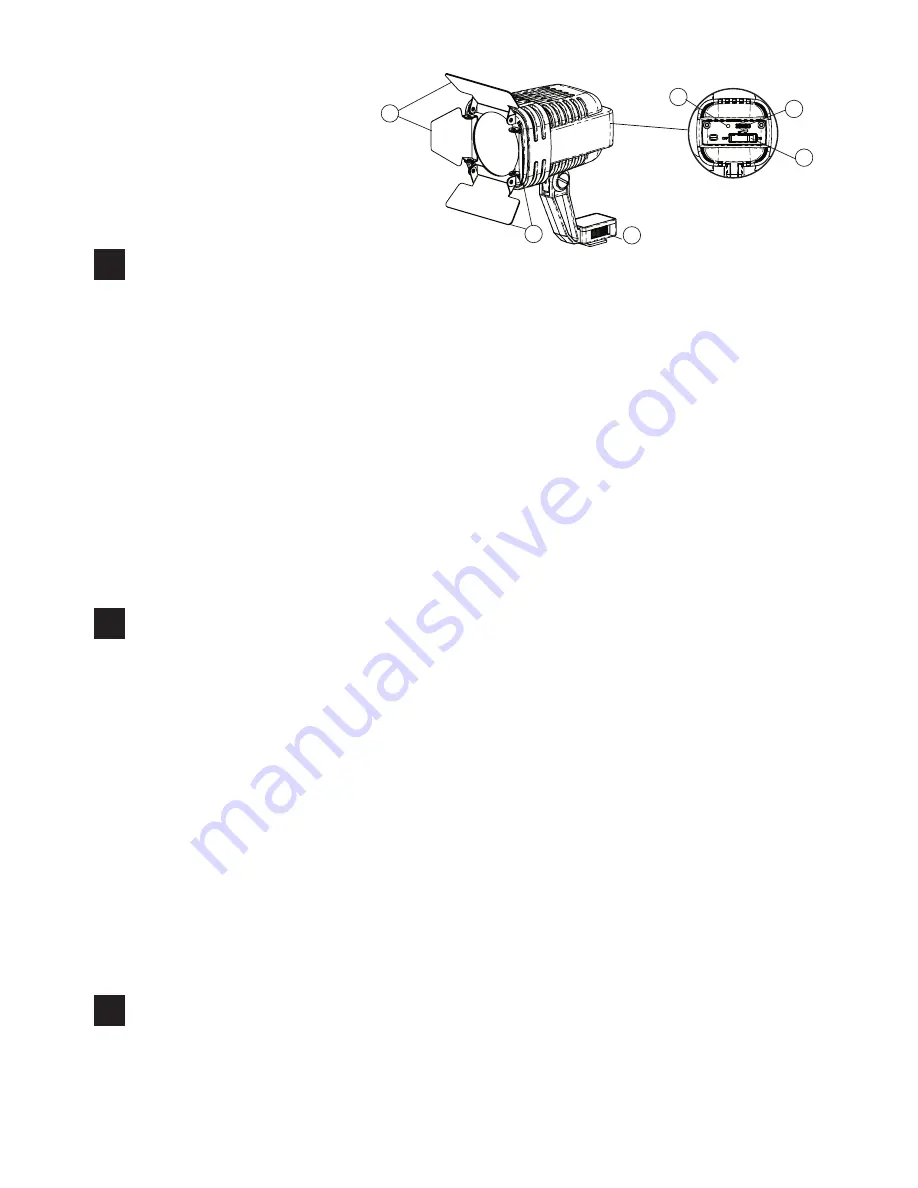
Parts diagram
Photography lights installed
Photographic lights removed
The use for photographic light
1. The opposite direction along the arrow anti-clockwise rotating locking to Release it
2. The opposite direction along pull out the photographic light, removed it
B
1. Rotating photographic lights, make it with the consistent direction of the camera lens
2. Photography lights interface will be inserted into the interface of the camera
concave-shaped
3. Clockwise rotating locking until locked in place
1. Video light insert the camera or the photographic camera appendix plug, then
tighten the knob.
2. Conect the video light cable to the power socket box plug.
3. Turn on the video light power switch.
4. Turn the Dimmer switch dial-twisting, to set the illumination to adjust location.
5. Turn the video light Shading plate angle.
Charge Guide
1. Connects the battery charger to 100V-240V alternating current supply.
2. Conect the charge to the power socket box plug to charge power.
3. When charge the battery charger guiding light is red, the charger guiding light turn
to green after 4-6 hours,the charge finished.
4. Take out the battery charger for next charge.
C
Replacement bulbs
Used of OSRAM brand bulbs
,
If you need to replace the OSRAM brand bulbs,
please contact your F&V dealer and the local F&V authorized repair center
,
When
buying bulbs please follow the code of accessories to order
。
1. Four flaps Barn door filter
2. Hot shoes fastening intortum
3. Mains switch on/off
4. Dimming knob(only 150D)
5.“Ready” Indicator
2
3
4
1
1
5


