M
cl
op
GND
+
L
-
+
N
L1 L2 L3 U
V
W
cl
op
GND
+
L
-
+
cl
COM op
Datum: 27-11-95
By:RvW / Ref:VJ
scale: nvt
Subject:
Update / by
check / by
M
V
W
U
N
L1 L2 L3 U
V
W
File:Aansl. MRK 2/GB
Version:
Sheet ... of ...
F1A/250 V
F1
F1A/250 V
1
2
3
4
5
6
7
8
9
10
1
2
3
4
5
6
7
op
1
2
3
4
5
6
7
8
9
10
1
2
3
4
5
6
7
cl
op
GND
+
L
-
+
cl
op
COM
CLOSE
OPEN
N /L2
CLOSE
OPEN
Limit switches
Close
P
Open
Computer
LOW VOLTAGE
HIGH VOLTAGE
Motor
Protection
Switch
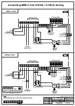
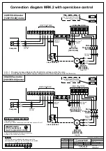
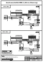
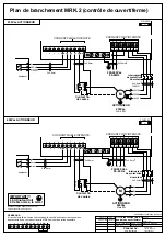
Connection diagram MRK.2 with open/close control
Limit switches
Close
P
Open
Computer
LOW VOLTAGE
HIGH VOLTAGE
Motor
Protection
Switch
REMARK:
Doc.no: 03.08.548.06
Connection MRK.2
with open/close control
MOTOR
240/1/50-60
[120/1/50-60]
max 4A
380-400Vac motor
240/1/50-60 motor
MOTOR
380-400Vac
[240/3/50-60]
max 4A
[240/3/50-60] motor
[120/1/50-60] motor
[L2][L1] [L2]
CLOSE
OPEN
[L3]
220/380-400Vac
[240/3/50-60]
L1 L2 L3
SEAL ALL CABLE ENTRIES
N
(T1)
(T2)
(T3)
240/1/50-60
[120/1/50-60]
[N] [H]
N/L2
L1
cl COM
F2
F1A/250 V
F1
F1A/250 V
F2
IMPORTANT!!!
All the equipment
must be grounded correctly
Connect Fancom equipment according to the prevailing
standards of the local electricity company.
Technical modifications reserved
Only for US and CAN models
Fuse only necessary when power
voltage is 240Vac (L1 and L2)
Fuse is F1A - 250V
Only for US and CA models
Fuse only necessary when power
voltage is 240Vac (L1 and L2)
Fuse is F1A - 250V
4x2,5mm2
12AWG
3x2,5mm2
12AWG
3x0,8mm
22AWG
3x0.8mm
22AWG
3x0.8mm
22AWG
4x2,5mm2
12AWG
5x2,5mm2
12AWG
3x0,8mm
22AWG
Fancom bv.
agro computers
P.O. box 7131
5980 AC Panningen
The Netherlands
US and CAN type:
when using 3 phase power supply 240/3/60 also connect L2 to N.
U.S. --> The power supply voltage and the transformer voltage must be the same
U.S. --> The frequency of the power supply voltage and the motor frequency must be the same.
If limit switches are included in the motor circuit, the
limit switch connections on the print should be connected.
29-3-00 / VJa JRe/VJa

