background image

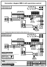
US and CAN type:
when using 3 phase power supply 240/3/60.
also connect L2 to N.

SEAL ALL CABLE ENTRIES

IMPORTANT!!!
All the equipment
must be grounded correctly

Connect Fancom equipment according to the prevailing
standards of the local electricity company.

M

N

L

N

L1 L2 L3 U

V

W

Datum: 27-11-95

By:RvW / Ref:VJ

scale:  nvt

Subject:

Update / by

check / by

Version:

Sheet ... of ...

M

V

W

U

N

L1 L2 L3 U

V

W

+

-

+

-

cl

op

GND

+

L

-

+

cl

COM op

1

2

3

4

5

6

7

8

9

10

1

2

3

4

5

6

7

cl

op

GND

+

L

-

+

COM op

1

2

3

4

5

6

7

CLOSE

OPEN

N/L2

CLOSE

OPEN

Limit switches

LOW VOLTAGE

HIGH VOLTAGE

Motor

Protection

Switch

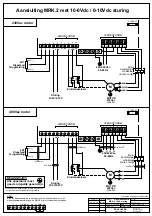
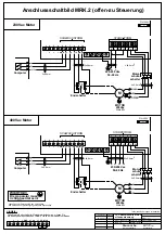
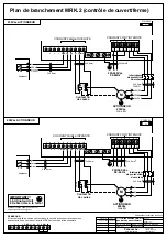
Connection diagram MRK.2 with 10-0 / 0-10Vdc control

Control

0-10V/10-0V

Doc.no: 03.08.548.07


Connection MRK.2

with 0 - 10V control

CLOSE

OPEN

Limit switches

LOW VOLTAGE

HIGH VOLTAGE

Motor

protection

switch

close (-)

open (+)

Control

0-10V/10-0V

4K7

Damper

position

feedback

380-400Vac motor
[240/3/50-60] motor

240/1/50-60 motor
[120/1/50-60] motor

MOTOR

240/1/50-60

[120/1/50-60]

max 4A

MOTOR

380-400Vac

[240/3/50-60]

max 4A

[L2] [L1] [L2] [L3]

220/400Vac

[240/3/50-60]

L1 L2 L3

240/1/50-60

[120/1/50-60]

[N] [H]

N/L2

L1

U.S. -->  The power supply voltage and the transformer voltage must be the same
U.S. -->  The frequency of the power supply voltage and the motor frequency must be the same.

REMARK:

(T1)

(T2)

(T3)

N

1

2

3

4

5

6

7

8

9

10

cl

Only for US and CAN models

Fuse only necessary when power

voltage is 240Vac (L1 and L2)

Fuse is F1A - 250V

F1A/250 V

F1

F1A/250 V

F2

F1A/250 V

F1

F1A/250 V

F2

Technical modifications reserved

Only for US and CA models

Fuse only necessary when power

voltage is 240Vac (L1 and L2)

Fuse is F1A - 250V

3x0.8mm

22AWG

3x0.8mm
22AWG

4x2,5mm2
12AWG

5x2,5mm2
12AWG

2x0.8mm
22AWG

3x0.8mm

22AWG

3x0.8mm
22AWG

2x0.8mm
22AWG

close (-)

open (+)

4K7

Damper

position

feedback

cl

op

GND

+

L

-

+

cl COM op

4x2,5mm2
12AWG

3x2,5mm2
12AWG

File:Aansl. MRK 2/GB

Fancom bv.

agro computers

P.O. box 7131

5980 AC Panningen

The Netherlands

If limit switches are included in the motor circuit, the
limit switch connections on the print should be connected.

29-3-00 / VJa    JRe/VJa

Summary of Contents for MRK.2

Page 1: ...MRK 2 HANDLEIDING MANUAL ANLEITUNG NOTICE INSTRUKCJA NL GB DE FR PL US CA...

Page 2: ...n dieser Anleitung vorzunehmen Fancom kann jedoch keine Garantie f r diese Anleitung bernehmen weder explizit noch implizit Das Risiko liegt ausschlie lich beim Benutzer Copyright 2000 Fancom B V Pann...

Page 3: ...gens de eisen van de algemene immuniteitsstandaard NEN EN 50082 1 en de surge immuniteitsstandaard EN 61000 4 5 4kV common mode en 2kV differentie mode De laagspanningsrichtlijn volgens de NEN EN 6095...

Page 4: ...in accordance with the requirements of the generic immunity standard NEN EN 50082 1 and the surge immunity standard EN 61000 4 5 4kV common mode and 2kV differential mode The low voltage guide accord...

Page 5: ...Anforderungen des allgemeinen Immunit tsstandards NEN EN 50082 1 des Surge Immunit tsstandards EN 61000 4 5 4kV Common Mode und der 2kV Differenzmode Die Niederspannungsrichtlinie entspricht dem NEN...

Page 6: ...igences de la norme d immunit g n rale NEN EN 50082 1 et de la norme d immunit surge EN 61000 4 5 4kV mode commune et 2kV mode diff rentiation La directive de basse tension selon la NEN EN 60950 R pon...

Page 7: ...y odporno ci NEN EN50082 1 oraz normy odporno ci surge EN 61000 4 5 4kV tryb og lny i 2kV tryb r nicowy Zalecenia niskiego napi cia zgodne z NEN EN 60950 Spe nia warunki zawarte w 1 Zalecenia niskiego...

Page 8: ...3 2 4 Limit switches GB 3 Connection diagrams 3 DEUTSCH Zur Anleitung DE 1 3 1 Einleitung DE 1 3 2 Technischen Daten DE 2 3 3 Montage und Installation DE 3 3 4 Endschalter DE 3 Anschlussschaltbilder 4...

Page 9: ...dviezen en opmerkingen met aanvullende informatie Voorzichtig Deze waarschuwing duidt op schade aan het product als u de procedures niet zorgvuldig uitvoert Voorzichtig Deze waarschuwing duidt op een...

Page 10: ...Sturing Type 10 0Vdc 0 10Vdc met EL print of open dicht 30Vac 60Vdc min 1A Terugmelding Potentiometer 4k7 20 Eindschakelaars Contact potentiaalvrij 30Vac 60Vdc min 1A Handbediening Draaischakelaar au...

Page 11: ...3 Monteer het eindstation n it binnen een afdeling vanwege de hand bediening 4 Monteer het eindstation op een hoogte waar u de handbediening kunt gebruiken 5 Monteer het eindstation op een vlakke ond...

Page 12: ...Klepstand Terugmelding OPM Als u de eindschakelaars in het motor circuit opneemt dan moet u de eindschakelaaraansluiting op de MRK 2 print met elkaar doorverbinden MOTOR 230Vac max 4A MOTOR 400Vac ma...

Page 13: ...RK 2 Open Dicht sturing MOTOR 230Vac max 4A 220 240Vac 50 60Hz MOTOR 400Vac max 4A N L N L1 L2 L3 230 400Vac 50 60Hz 230Vac motor 400Vac motor cl COM op BELANGRIJK Alle apparatuur moet goed en degelij...

Page 14: ...e of contents The following symbols are used in this manual Suggestions advice and notes with additional information Caution The product could be damaged if the procedures are not followed carefully C...

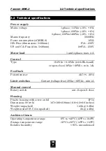
Page 15: ...Control Type 10 0Vdc 0 10Vdc with EL board or open close 30Vac 60Vdc min 1A Feedback Potentiometer 4k7 20 Limit switches Contact voltage free 30Vac 60Vdc min 1A Manual control Rotary switch aut 0 open...

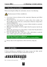
Page 16: ...are present because of the manual control 4 Mount the end station at such a height that the manual control can be used 5 Mount the end station on a flat surface ensure that the gland nuts are at the b...

Page 17: ...60 motor MOTOR 240 1 50 60 120 1 50 60 max 4A MOTOR 380 400Vac 240 3 50 60 max 4A L2 L1 L2 L3 220 400Vac 240 3 50 60 L1 L2 L3 240 1 50 60 120 1 50 60 N H N L2 L1 U S The power supply voltage and the t...

Page 18: ...RIES N T1 T2 T3 240 1 50 60 120 1 50 60 N H N L2 L1 cl COM F2 F1A 250 V F1 F1A 250 V F2 IMPORTANT All the equipment must be groundedcorrectly Connect Fancom equipment according to the prevailing stand...

Page 19: ...leitung Vorschlag Hinweis oder Bemerkung mit extra Information Vorsicht Eine Warnung die auf Schaden am Produkt hinweist falls die Anweisungen nicht sorgf ltig befolgt werden Vorsicht Eine Warnung die...

Page 20: ...A Steuerung Typ 10 0Vdc 0 10Vdc mit EL Einsteckkarte oder Offen Zu 30Vac 60Vdc min 1A R ckmeldung Potentiometer 4k7 20 Endschalter Kontakt spannungsfrei 30Vac 60Vdc min 1A Handbedienung Drehschalter a...

Page 21: ...der Hand Bedienung 4 Die Endstation in Augenh he montieren so dass die Handbedienung gew hrleistet ist 5 Die Endstation auf einem flachen Untergrund montieren und daf r sorgen dass die Kabelverschraub...

Page 22: ...CHSTROM STARKSTROM Motor schutz schalter Zu Offen Steuerung 10 0V 0 10V 4K7 Klappenposition HINWEIS 400Vac Motor 230Vac Motor MOTOR 230Vac max 4A MOTOR 400Vac max 4A 220 240 Vac 50 60 Hz 230 400 Vac 5...

Page 23: ...548 10 Anschlussbild MRK 2 offen zu steuerung MOTOR 230Vac max 4A ZU OFFEN ZU OFFEN 220 240 Vac 50 60 Hz 400Vac Motor 230Vac Motor MOTOR 400Vac max 4A N L N L1 L2 L3 230 400 Vac 50 60 Hz cl COM op op...

Page 24: ...s dans cette notice Suggestions conseils et remarques avec des informations suppl mentaires Attention Cet avertissement fait allusion aux dommages au produit au cas o vous n ex cutez pas attentivement...

Page 25: ...ax 4 A Commande Type 10 0Vdc 0 10Vdc avec acrte EL ou ouverture fermeture 30Vac 60Vdc min 1A Asservissement Potentiom tre 4k7 20 Contacts fin de course libres de tension 30Vac 60Vdc min 1A Commande ma...

Page 26: ...amais monter le p riph rique dans une salle cause de la commande manuelle 4 Installer le p riph rique une hauteur convenable o l on pourra utiliser la commande manuelle 5 Installer le p riph rique sur...

Page 27: ...NT FORT INTENSTE Interrupteur de protection du moteur Contr l 0 10V 10 0V 400Vac ACTIONNEUR 230Vac ACTIONNEUR FERME OUVERT FERME OUVERT ACTIONNEUR 230Vac max 4A ACTIONNEUR 400Vac max 4A 220 240Vac 50...

Page 28: ...moteur Doc no 03 08 548 08 Branchement MRK 2 contr le de ouvert ferme ACTIONNEUR 230Vac max 4A 220 240Vac 50 60Hz FERME OUVERT Ferme Ouvert 400Vac ACTIONNEUR 230Vac ACTIONNEUR ACTIONNEUR 400Vac max 4A...

Page 29: ...suje si nast puj ce symbole Sugestie rady i uwagi z dodatkow informacj Uwaga Produkt mo e ulec uszkodzeniu gdy procedura nie jest prowadzona z dostateczn uwag Uwaga Je eli procedura nie zostanie uwa n...

Page 30: ...k EL lub otwarte zamkni te 30Vac 60Vdc min 1A Sygnalizacja zwrotna Potencjometr 4k7 20 Wy czniki kra cowe bez napi cia 30Vac 60Vdc min 1A Obs uga r czna Prze cznik na stronie czo owej aut 0 open 0 clo...

Page 31: ...Nie montuj urz dzenia w pomieszczeniu gdzie znajduj si zwierz ta ze wzgl du na obs ug r czn 4 Umie urz dzenie na takiej wysoko ci by obs uga r czna by a dogodna 5 Zamontuj urz dzenie na p askiej powie...

Page 32: ...0 10Vdc lub 10 0Vdc MA EJ MOCY Zasilanie 220 240Vac 50 60Hz Zasilanie 220 400Vac 50 60Hz L2 L3 N L1 ZABEZPIECZ WLOTY KABLOWE UWAGA JE ELI WY CZNIKI KRA COWE S W CZONE DO OBWODU REGULACJI SILNIKA CZNI...

Page 33: ...K EL 220 240Vac max 4A SILNIK EL 380 400Vac max 4A Zasilanie 220 400Vac 50 60Hz d d 31 05 95 By VJ Ref WH File Aansl MRK 2 PL Program CANVAS 3 5 Fancom bv agro computers P O box 7131 5980 AC Panningen...

Reviews: