11
8.2.2.3.2 Preparation of the back casing
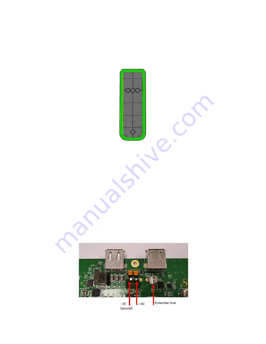
1. Once the fixing holes and cable ducts have been identified and opened on the rear face,
proceed to pass the cables and fix the back casing against the surface. The back casing
is supplied with a seal which makes it possible to seal in the event of irregularities on the
surface, make sure to place it during the installation.
2. The rear phase has two USB-A female connectors, to connect external devices (dongles
or USB cables). If necessary, install the elements on the USB sockets and connect the
data cables, if necessary.
These devices will be powered and connected to the central Android system once the
front casing is placed and the entire validator closed. Please note that the available USB
interface is type 2.0, and the current delivered by each port is limited to 500mA.
3. Before making the electrical connection, make sure that the power supply is
switched off during the entire intervention.
a. Strip the power supply wires. Crimp (if needed) the wires.
b. On the terminal block, connect the VDC wires, respecting the marking on the
electronic board (“+” or “24V” marking for the positive wire and “-” or “GND”
marking for the ground wire). The terminal block secures the wire by a simple
press: push the orange buttons to insert the end of the wire. Nominal working
voltage is 12 VDC or 24 VDC.


