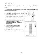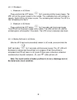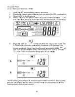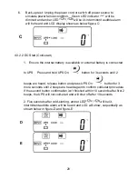
28
4.3.3 UPS Default and Optional Settings
4.3.3.1 Verify the UPS is in Standby. Press the On
button and Next Page
buttons simultaneously for approximately 3 seconds. The buzzer
will sound twice and the LCD will display figure Q1, indicating that the UPS
is in setting mode.
4.3.3.2 To scroll through the options, use the Next Page
button. Refer to
section 4.3.2.5.
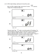
4.3.3.3 Except for Buzzer (figures Q1 and Q2) and Self-test (figures R1 and R2)
all of the other default settings may be changed by pressing the Previous
Page
button.
4.3.3.4 Figures S1 and S2 indicate the bypass input acceptable window which
follows the inverter output voltage setting. For example, if the output voltage
setting is 120Vac, the Bypass Sensitivity Low range is 120Vac ±15%, i.e.,
102 - 138 Vac.
4.3.3.5 Figure T indicates the bypass frequency window of the Inverter Output.
The acceptable setting values are ±3 Hz and ±1 Hz.
4.3.3.6 Figure U indicates the acceptable Inverter Output Voltage. Possible
values are 100, 110, 115, 120, or 127 Vac.
4.3.3.7 Figures V1, V2, V3 and V4 indicate the operation modes of the UPS.
Possible values are Online (STD) mode, Eco (Economical) mode, fixed 50
Hz Output and fixed 60 Hz Output mode.
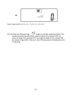
4.3.3.8 Figure W indicates the adjustment of the Inverter Output, which may be
set to 0%, +1%, -1%, +2%, -2%, +3%, or -3%.
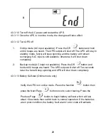
4.3.3.9 After changing settings you must scroll to the “End” screen (figure X) and
then press the Enter
button to save all of your changes.


