background image


21 

4.3.2.3 LCD Measurements 


1.  UPS measurements can be checked after the UPS has started by pressing the 

Next Page

  button. The display sequence is shown below in figures F 

through M, respectively. 


F


G


H


I


Summary of Contents for SG1.5K-1SC

Page 1: ...rmation contained herein is proprietary to Falcon Electric Inc and shall not be reproduced or disclosed in whole or in part or used for any reason except when such user possesses direct written authorization from Falcon Electric Inc The statements contained herein are based on good faith assumptions and provided for general information purposes only These statements do not constitute an offer prom...

Page 2: ...n 13 4 1 Unpacking 13 4 2 Installation Location 16 4 3 Operation 17 5 UPS System Architecture and Operating Modes 31 6 Maintenance Guide 32 6 1 Troubleshooting 32 6 2 Error Code Definitions 35 6 3 Maintenance 35 7 Communication Software 36 7 1 Hardware Setup 36 7 2 Software Installation 36 8 Optional Communication Cards 37 8 1 R2E second RS 232 card 37 8 2 USE USB card 37 8 3 DCE Dry Contact card ...

Page 3: ...ght Do not install the UPS in a flammable or otherwise hazardous environment Avoid vibration and areas subject to physical impact The maximum UPS output load in watts must never exceed that shown on the UPS rating label NEVER CONNECT equipment that could overload the UPS or demand half wave rectification from the UPS output for example electric drills vacuum pumps or hair dryers 6 To prevent overh...

Page 4: ...trical shock and short circuit current The following precautions should be observed when working on batteries a Remove watches rings or other metal objects b Use tools with insulated handles c Wear rubber gloves and boots d Do not lay tools or metal parts on top of the batteries e Disconnect charging source prior to connecting or disconnecting battery terminals f Determine if battery is inadverten...

Page 5: ...iendly plug and play design allows hassle free installation 5 Built in maintenance free sealed batteries minimize the need for after sales service 6 To protect the unit from overloading the UPS will automatically switch to bypass mode in 30 seconds if loading is above 105 of rated capacity It will automatically switch back to inverter mode once the overload condition ceases 7 Should the output bec...

Page 6: ...tages 5 Our smart battery management system maximizes overall battery life 6 Our Active Power Factor Correction control function constantly maintains the UPS input power factor at 0 9 for superb energy efficiency 7 Our Selectable Bypass input voltage tolerance sensitivity low high prevents under or over voltage being supplied to the loads in bypass mode The selectable voltage ranges are i Bypass S...

Page 7: ...uzzer and show an Error Code Do not hold for 1 second OFF UPS Power Off Switch Press and hold until the buzzer beeps Self Test a Commands the UPS to perform a battery self test Press and hold until the buzzer beeps b Battery and Load Display Function Mode Do not hold for 1 second Manual Bypass Press the ON key and Self Test key simultaneously for 3 seconds to transfer from Inverter to Bypass The b...

Page 8: ...or Code Function Mode Overload LED 1 Indicates UPS is overloaded 2 In Error Code Function Mode indicates Error Code 16 Site wiring fault LED 1 Indicates reversed polarity or high neutral ground voltage 2 In Battery and Load Function Mode indicates load capacity is 100 3 In Error Code Function Mode indicates Error Code 8 Outlet 1 LED 1 Indicates UPS Outlets 1 are enabled and ready to supply loads T...

Page 9: ...ng window 90Vac 150Vac the LED flashes to indicate that the utility input voltage is within the acceptable window 60Vac 90Vac Green LED lights up to indicate there is an output available at Programmable Outlet 1 Programmable Outlet 2 Amber LED lights up to indicate the Bypass Input is normal or continuously blinks when UPS is in bypass mode UPS Fault LED UPS On Alarm Silence UPS Inverter output of...

Page 10: ...To transfer in and out of bypass mode verify the UPS is in online mode and then press UPS On and Previous Page buttons simultaneously for approximately 3 seconds The bypass LED and audible alarm will activate approximately every 2 seconds indicating the UPS is in bypass mode Battery back up is not available while the UPS is in bypass mode ...

Page 11: ...pass Bypass Abnormal at ECO mode 2 Utility Input Abnormal 3 Site Wiring Fault 4 Buzzer Silent 5 UPS Overload 6 Service Mode Disabled 7 UPS Fault Alarm 8 UPS Flow Chart 9 3 Digit Measurement Display 10 Indicates the item to be measured 11 Battery Abnormal 12 Battery Low 13 Indicates Battery Self test ...

Page 12: ...32 port 4 Fan 5 External battery connector 6 Slot for optional communication cards 7 AC input power line cord 8 Utility input circuit breaker 9 Output circuit breaker for 2 outlets 10 Programmable Output Receptacles 11 Communication Surge Protection 700VA 1kVA 1 5kVA 2kVA 3kVA ...

Page 13: ...oftware All communication ports including optional cards can be active and used simultaneously to monitor the UPS status However only one communication interface the one with the highest priority can control the UPS at a time The priorities of these communication interfaces are listed below highest priority first 1 EPO input port 2 Optional interface card 3 USB 4 RJ11 RJ45 Communication surge prot...

Page 14: ...ng shipment Notify the forwarder and Falcon Electric if there is damage The packaging is recyclable and reusable 1 After removing the packing foam please be careful handling the UPS while it is still in the plastic bag The plastic is slippery and the UPS could fall and cause an injury 2 Check for the following standard package contents in addition to the UPS itself A User s Manual CD B UPSilon Mon...

Page 15: ...14 4 1 1 Installation Instructions Tower installation Rack Mount installation Step 1 Step 2 ...

Page 16: ...15 Step 3 ...

Page 17: ...ts 1 Keep at least 8 inches of clearance beyond the rear panel of the UPS 2 Do not block the air flow to the ventilation louvers of the unit 3 Ensure that the installation site is free from excessive dust and the ambient temperature and humidity are within the specified limits 4 Do not place the UPS in a dusty or corrosive environment or near any flammable objects 5 This UPS is not designed for ou...

Page 18: ...he loads to the UPS to ensure that the batteries are working properly To do this switch off the AC power source when the UPS is on The LED on the front panel will turn off the LED will illuminate and the buzzer will activate indicating that the UPS is in Battery Mode Connect a non critical load to the UPS outlets to confirm that the batteries are supplying power Repeat the test by switching the AC...

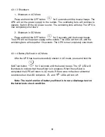
Page 19: ... to the outlets The LEDs will turn off and the ventilating fans will stop after 10 seconds The UPS is now completely shut down 4 3 1 4 Battery Self test in AC Mode After the UPS has been successfully started in AC mode press and hold the Self Test button for 5 seconds until the buzzer beeps The LED will illuminate to indicate that the self test is in progress When the self test is completed the UP...

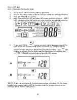
Page 20: ... will start spinning 5 Press the UPS On button and hold until 2 beeps are heard The UPS will switch to online mode within 5 seconds LCD display will be shown as listed in figure A and then figure B sequentially LEDs will light up to indicate that the Utility and the Bypass are normal And then LED remain lit during figure B LCD display A B NOTE When you see figure B the start up procedure is finish...

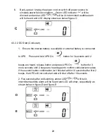
Page 21: ...tery is connected to UPS Press and hold UPS On button for 3 seconds until 2 beeps are heard release button and press UPS On button for 3 more seconds until 2 beeps are heard again to confirm cold start procedure If the second button confirmation isn t finished within 10 seconds after first 2 beeps the UPS will not cold start and will shut off after 10 seconds 2 Five seconds after cold starting amb...

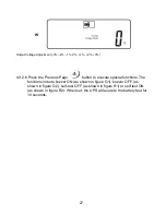
Page 22: ...21 4 3 2 3 LCD Measurements 1 UPS measurements can be checked after the UPS has started by pressing the Next Page button The display sequence is shown below in figures F through M respectively F G H I ...

Page 23: ...22 J K L M ...

Page 24: ...o release the UPS from locked up status is as follows 1 Check and record the error code 2 Reference sections 6 1 and 6 2 for troubleshooting and error codes If the problem persists contact Falcon Electric for further assistance 3 Press the Off button and hold for 5 seconds until 2 beeps are heard 4 Unplug AC input power cord or turn off AC mains power source switch 5 After the UPS completely shuts...

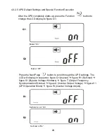
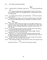
Page 25: ...zer On Q2 Buzzer Off Press the Next Page button to scroll through the UPS settings The LCD will display in sequence figure Q1 buzzer figure R1 Self test figure S1 Bypass Voltage Windows figure T Output Frequency Synchronization Window figure U Inverter Output Voltage figure V1 UPS Operation Mode figure W Inverter Voltage Adjust R1 Self test is not On R2 Self test is On ...

Page 26: ...ltage is adjusted to low range 15 of UPS output setting S2 Bypass Voltage is adjusted to high range 10 of UPS output setting T Frequency Window is 3 Hz 3 Hz or 1 Hz U Inverter Output Voltage 100 110 115 120 or 127Vac ...

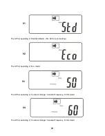
Page 27: ...ng in Standard Mode 50 60Hz Auto tracking V2 The UPS is operating in Eco mode V3 The UPS is operating in Constant Voltage Constant Frequency 50 Hz mode V4 The UPS is operating in Constant Voltage Constant Frequency 60 Hz mode ...

Page 28: ...ious Page button to execute special functions The functions include buzzer ON as shown in figure Q1 buzzer OFF as shown in figure Q2 self test OFF as shown in figure R1 or self test ON as shown in figure R2 When set the UPS will execute the battery test for 10 seconds ...

Page 29: ...ws the inverter output voltage setting For example if the output voltage setting is 120Vac the Bypass Sensitivity Low range is 120Vac 15 i e 102 138 Vac 4 3 3 5 Figure T indicates the bypass frequency window of the Inverter Output The acceptable setting values are 3 Hz and 1 Hz 4 3 3 6 Figure U indicates the acceptable Inverter Output Voltage Possible values are 100 110 115 120 or 127 Vac 4 3 3 7 ...

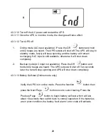
Page 30: ... it will shut down completely 2 Backup mode AC input not available Press the Off button and hold until 2 beeps are heard The UPS output will shut off Ten seconds later the fan will stop spinning and UPS will shut down completely 4 3 3 13 Battery Self test Online mode only Verify the UPS is in online mode Press the function button then press the Next Page button once to select testing Press the Pre...

Page 31: ...bited Long continuous beep Control keypad error Long continuous beep UPS fault loads continue to be supplied via Inverter or Bypass Single beep every 2 seconds In battery mode Single beep once per second Battery low Quick and short successive beeps Confirm RS 232 port receiving Two quick and short beeps Service mode verified One quick and short beep ...

Page 32: ...UPS Operating Mode LEDs Normal Online UPS detects AC power in approximately 5 seconds LEDs on the panel will blink and fans will start Press the ON button for 1 5 seconds The UPS starts up normally LEDs will be lit Abnormal under over voltage or absent Rectifier and charger stop operating Battery discharges via DC DC boost circuit and powers the inverter Loads continue to receive power from Invert...

Page 33: ...up Otherwise contact Falcon Electric 2 Overload 2 Disconnect some non critical loads from the UPS output until the overload ceases Check if there is any short circuit between cables due to broken cable insulation Replace the cables if necessary 3 Er11 UPS over temperature 3 Remove any objects obstructing the ventilation louvers Verify that the cooling fans are working properly Contact Falcon Elect...

Page 34: ...itches back and forth between battery and utility modes 1 A faulty power strip is connected to the UPS 2 See if there is any damage to the utility wall receptacle or if the cord plug is faulty 1 Do not use the power strip 2 Replace the wall receptacle cord plug Strange noise or smell Immediately shut down the whole system Disconnect the power from the UPS and contact Falcon Electric for service UP...

Page 35: ...rror codes 1 2 4 8 and 16 are represented by the 4 bar LEDs 25 50 75 and 100 and the Overload LED Each LED represents a number as shown in the figure below For example the figure below shows the 25 50 and 100 bar LEDs lit The error code is therefore 8 2 1 11 or Er11 which indicates that the UPS is in over temperature condition ...

Page 36: ...cted Er07 EPO mode activated Er11 UPS over temperature Er12 Inverter overload Er14 Fan Failure Er39 Battery not present at start up or utility input voltage is below 90Vac Er28 Overload Bypass condition 6 3 Maintenance 1 Clean dust from the ventilation louvers and fan guards on the rear panel 2 Turn off the UPS and wipe the casing with a damp cloth Be careful to avoid getting water in the UPS 3 Pe...

Page 37: ...or optional interface cards please refer to Chapter 8 2 Connect a male RS 232 connector or a USB cable to the UPS communication port Connect the female RS 232 connector or the other end of the USB cable to the computer Note USB cable is supplied 7 2 Software Installation Please refer to the software user s manual ...

Page 38: ...or interface settings and pin assignments please refer to section 3 3 1 8 1 3 Installation Location Communication Option Slot 8 2 USE USB card 8 2 1 CN1 is for USB 8 2 2 For the communication protocol definition please refer to section 8 4 2 8 2 3 Installation Location Communication Option Slot ...

Page 39: ...unction during a power loss apply 6 25VDC to pins 9 and 10 for 5 seconds and the UPS will shut down 8 3 3 The capacity of each relay contact is 40 VDC 25 mA 8 3 4 Installation Location Communication Option Slot 8 3 5 Flexible signal output for N C Normally Closed or N O Normally Open contact by shorting pins1 2 or pins 2 3 from JP1 5 8 3 6 The shutdown function will be enabled one minute after pow...

Page 40: ...the card 8 4 1 2 Installation Location Communication Option Slot 8 4 2 USB Designations The USB communication protocol definition is listed below 1 Complies with USB version 1 0 1 5 Mbps 2 Complies with USB HID version 1 0 3 Pin Assignments For USHA SNMP HTTP Card information contact Falcon Electric 1 VCC 5V 2 D 3 D 4 Ground ...

Page 41: ...UPS requires service or should any other technical support be required write call fax or email Falcon Service Falcon Electric Inc 5116 Azusa Canyon Road Irwindale CA 91706 Service 800 842 6940 Voice 626 962 7770 Fax 626 962 6850 Email service falconups com www falconups com ...

Page 42: ...ct ii unauthorized repairs or modifications or use of unauthorized parts iii acts or events outside of Falcon s control such as fire accidents impacts iv normal wear and tear such as cleaning and replacement of batteries The warranty is null and void if i the product is used in conjunction with life support equipment ii The factory seal is broken or shows signs of tampering or iii the battery is all...

Reviews: