BOLERO40 Series Promotion Kit
Version 1.0.1
This confidential document is a property of FALCOM GmbH and may not be copied or circulated without previous permission.
Page 10 of 21
3.2.2
Installing the FALCOM Workbench software and start evaluation
The following list shows the hardware requirements for Workbench software:
(a)
PC with 700 megahertz or higher processor Intel Pentium II or compatible processor recommended
(b)
512 MB of RAM or higher recommended (512MB min. supported; may limit performance and some
features)
(c)
90 megabytes (MB) of available hard disk space (recommended 2 gigabytes)
(d)
Keyboard and Mouse.
To be able to test your device with factory preloaded configuration or to change this configuration and load
your configuration into the BOLERO40, you need to install the
Workbench
evaluation software. Go to the
link below and download it: http://www.falcom.de/support/software-tools/falcom-workbench/
An install
shield will guide you through the installation. An integrated online help can be found after the installation
completes.
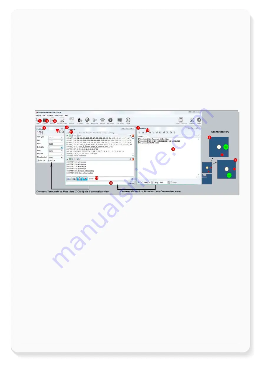
Figure 9:
FALCOM Workbench software.
1.
After completing the installation, start the
Workbench.exe
by double-clicking on it. Open a new
COM
Port
from the Toolbar
(1)
, on the
COM Port view
(2)
choose the Port where BOLERO45/41 is
connected (go to Device Manager > Ports > USB Serial Port (COMxx), where
xx
is the COM port to use),
define the port settings (
115200
bps,
8
Data bits,
No
Parity bit,
1
Stop bit,
None
Flow control) and
finally, click the connect (play) icon
(2.1)
to open that COM Port. You can also get an online help in
HTML format if you click "
Help
" button on the upper-right corner.
2.
Open a new
Console
from the Toolbar
(3)
, click on the
Console1
(4)
, then go to
Connection view
and
click on
COMPort
(5).
3.
Open a new
Editor
from the Toolbar
(6)
, click on the
Editor1
(7)
, then go to
Connection view
and click
on
Console1
(8).
4.
To send commands to the BOLERO45/41 device, type them on the
Editor
(9)
and then click on
Start
sending configuration
(10)
or double click with left mouse each configuration line on the
Editor
(9)
individually.
5.
To see all events generated by the BOLERO45/41 device, either open a new console “Console2” or on
the Console1
(4)
, click “Add”
(11)
, type the text “GPEVENT” on input field
(12)
, finally click the button
(13 )
“Filter incoming”. A description how to operate with the Control-Box is given in chapter 4.
6.
You have to load/save your configuration into your device before installing the device in the vehicle.
How to send data to a TCP-Server or SMS messages to a phone number/SMS server and how to
reconfigure the loaded configuration on the device, refer to the Related Documents [1]. A description
how the firmware on the BOLERO45/41 works is given in chapter 5.1
3.2.3
Accessing online documentation
R
eferences to the online documentation are listed in chapter
2.2
, related documents.


