

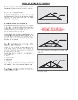


Before you begin
The distance between the joists should be the same as the width of installation opening. All cut joists must be attached to the joists that have not
been cut.
WARNING!
For your own safety mind all dangerous elements above your head.
Do not sit on the ceiling - it is not designed do carry load.
Only joists will withstand load. In order to make a working area place several boards across the ceiling joists.
VII. FRAMING THE INSTALLATION OPENING
If none of the joists were cut proceed to section
ď
single header
Ē
.
If one or more joists were cut proceed to section
ď
double headers
Ē
on page 8.
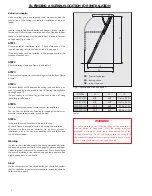
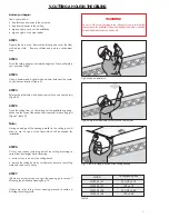
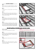
Single headers
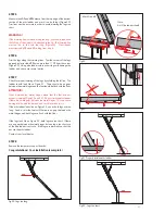
STEP 1
Measure the distance between the ceiling joists. The measurement
should be done perpendicular to the joist (Figure12).
STEP 2
Cut 2 boards for headers to the measured length. Use timber
material similar in size to the joists.
STEP 3
Position the header at one end of the installation opening
(Figure13). The header must tightly fit between the joists. If
needed use a hammer to position the header.
Step 4
Align the header at 90
o
angle to the joists and drive 3 nails (16D)
at each end.
STEP 5
Position the second header 47
Ē
apart from the first one for LWS-
P 22/47, LWS-P 25/47 or 54
Ē
for LWS-P 22/54, LWS-P 25/54
and repeat step 4 (Figure 14).
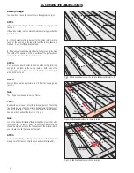
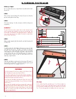
STEP 6
The frame must have four sides where the headers are two of them.
If the ceiling joists are positioned as the other two sides check the
angles by measuring the diagonals. Both measured dimensions
should be within 1/8
Ē
to consider them equal.
Proceed to section 8
ď
installation of temporary support boards
Ē
.
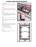
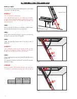
If the ceiling joists do not make the other two sides of the frame,
you should install one or two wooden elements in order to make
the frame in the ceiling opening. Proceed to section
ď
installation of
stringers
Ē
.
P
Fig.12.
P
- Distance between the ceiling joists.
ceiling joist
nails
header
Fig.13. Nail the header at both ends.
ceiling joist
47
"
(LW
S-P 22/4
7;
LW
S-P 25/4
7)
D1 D2
nails
header
header
D1=D2
54
"
(LW
S-P 22/5
4; L
W
S-P 25/5
4)
Fig.14.
Installing the headers
7


