background image


Ultrasonic Level Transmitter


ULM84 Series User Manual


Dec.2020    


Page  14 of 21 


www.faraboard.com


FAHM Co
Industrial Automation 
Doc. ULM84 Rev.99-12 


Define Level Lookup Table Values (

P15    Length/ Volume Table

This menu is activated if in menu #12 the method of volume calculation by level based on a lookup table is 
selected.


In  this  case,  the  user  must  apply  a  minimum  of  2  and  a  maximum  of  10  level  /  volume  pairs  to  the 
equipment, depending on his knowledge of the tank. How many level / volume pairs the user allocates to 
complete the lookup table depends on their recognition and knowledge of the tank, but it is important to 
apply the values in this table as follows:


1-


Enter the settings of this menu and enter the corresponding level and volume values as the first data. 

2-


After confirming the values of the first level/ volume pair, enter the level value and the corresponding 
volume as the second data. 

3-


After confirming the above values and also up to a maximum of 10 pairs, if the user wants to continue 
to  complete  the  table,  which  is  similar  to  the  first  two  steps,  apply  the  values  in  each  step  and  by 
confirming the settings, enter another pair to receive information. For example, suppose the user has 
applied 6 level / volume pairs to the equipment; Then - when you go to the next menu, you will see that 
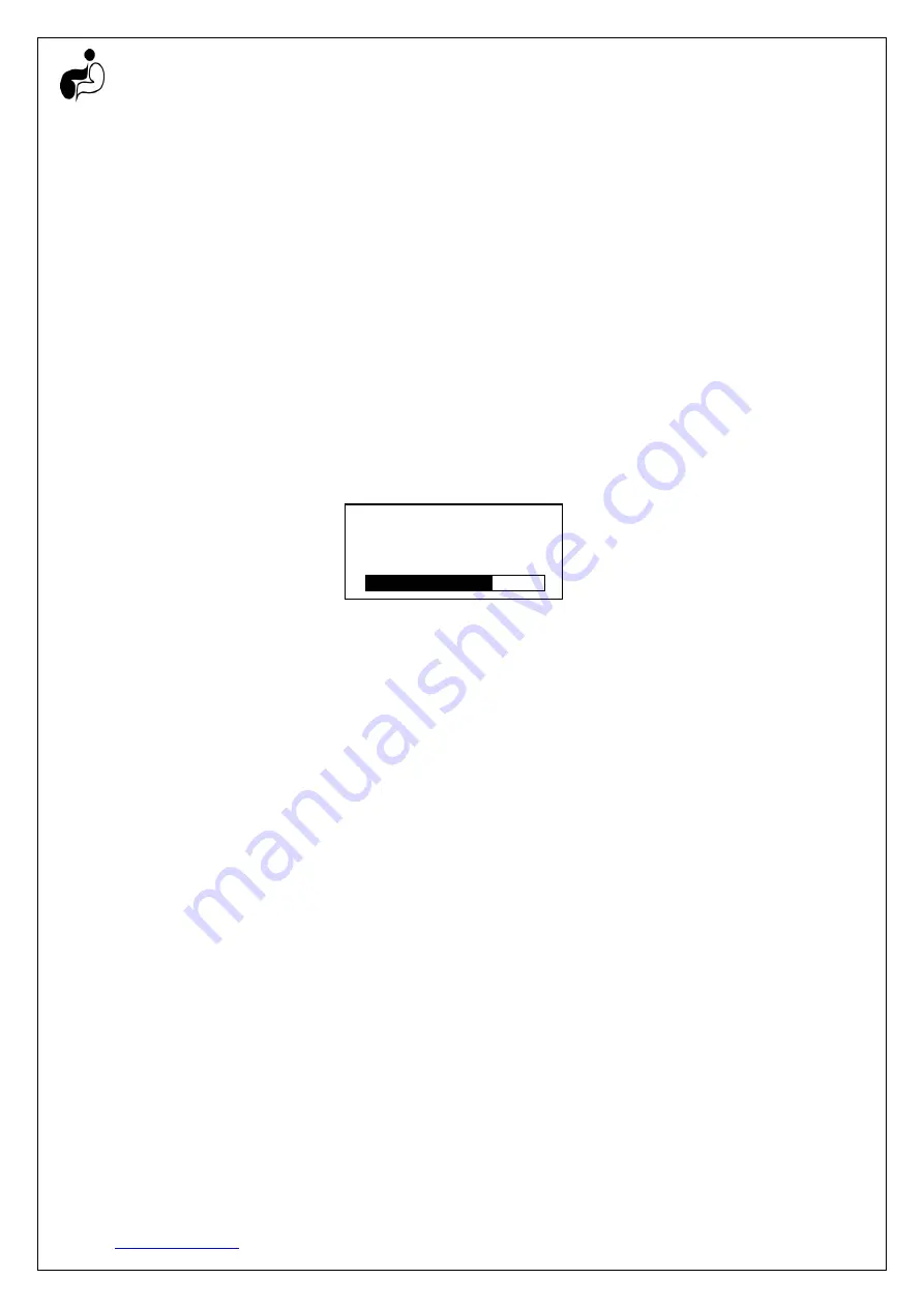
the display shows the following screen:


---- Basic Menu ---


P15L7>           -1.0000 METER 
P15V7>          -1.0000 METER3 


16.342 mA


77.14%


Figure 20 - Adjusting the values of the seventh level / volume pair


At this point, if the user wants to provide information on the seventh level / volume pair, does it the same 
as before; But if he concludes that it is not necessary to continue the process of completing the table, it is 
required


to


simply


keep


the


newly


created


pair


(for


example,


the


seventh


pair


here)


in


the


same


state


(-1, -1); 

In this way, the equipment will know that it must do the work of determining the volume of liquid in the 
tank according to the previous data (here 6 pairs). 


Define Liquid Level to Activate High-High Alarm (

P20    Alarm Limit HI-HI

The user can set a value commensurate with the level at which he expects this alarm to work; If the fluid 
level exceeds the above level, this alarm will work; To return it to normal, the fluid level must be less than 
the value set in the "P16 Alarm Buffer" menu

.

 Also, by opening the back cover of the equipment, the user 

can see the terminals of this alarm as shown in Figure 21. 


Define Liquid Level to Activate High Alarm (

P21    Alarm Limit HI

The user can set a value commensurate with the level at which he expects this alarm to work; If the fluid 
level exceeds the above level, this alarm will work; To return it to normal, the fluid level must be less than 
the value set in the "P16 Relay Buffer" menu. 
By opening the back cover of the equipment, according to Figure 21, the terminals of this alarm can be 
seen. 


Define Liquid Level to Activate Low Alarm (

P22    Alarm Limit LO

The user can set a value commensurate with the level at which he expects this alarm to work; If the fluid 
level is lower than the above level, this alarm will work; To return it to normal, the fluid level must be higher 
than the value set in the "P16 Relay Buffer" menu. 
Also, by opening the back cover of the equipment, the user can see the terminals of this alarm as shown in 
Figure 21.


Summary of Contents for ULM84 Series

Page 1: ...Ultrasonic Level Transmitter ULM84 Series User Manual Dec 2020 Page 1 of 21 www faraboard com FAHM Co Industrial Automation Doc ULM84 Rev 99 12 Ultrasonic Level Transmitter ULM84 User Manual ...

Page 2: ...A Output Current Output HART Protocol M20x1 5 Electrical Connection G1 5 G2 G3 Flange Process Connection Plastic Aluminum Housing Materials Polyurethane ETFE PTFE Sensor Head Materials 20 85 C IP68 Ambient Temperature Environmental Conditions 40 100 C Process Temperature Process Conditions 0 8 2 0 bar Process Pressure 3 Installation Figure 1 Transmitter s installation place Please pay attention to...

Page 3: ...ule 5 it should be installed on left part with a suitable distance from the wall rule 6 and from the liquid level rule 1 Finally regarding tank conditions and choosing the correct installation location the transmitter is mounted using bracket flange or thread nut Figure 3 Mounting methods 4 Wiring There are two possible ways to do the wiring If the goal is to read the transmitter s current or to a...

Page 4: ... 8 Error NAN display mode The following reasons may also cause to display one of errors in Figure 9 a If the time passed the last level detection by the transmitter is more than Alarm Time1 and the transmitter couldn t detect the level anymore the left screen of Figure 9 would be displayed b If because of defect in the sensor itself or its connecting cable the transmitter failed to reach the senso...

Page 5: ... to change the numbers signs or choices of the parameter And finally when calibrating the 20 mA current output P02 20 mA Setup you can press the key for 2 to 10 seconds to accept just detected level as the reference for 20 mA current output Please note that if you hold the key for less than 2 seconds or more than 10 seconds the device ignores it Down Key In lists this key will take us to next scre...

Page 6: ...o choose to calculate the mass a The volume is calculated based on the level and the mass calculated based on the volume given that the user has provided the density This method makes sense when the shape of the tank is symmetrical b The user provides a lookup table of level volume pairs max 10 entries and the volume is calculated using this lookup table then the mass is calculated based on the vo...

Page 7: ...he main value to be displayed Echo Curve Display Mode In this mode all received waves by the device in a defined time range are displayed also by drawing the Threshold Level line the user can see the waves that are identified as target levels In addition to the curve there are Noise to Signal Ratio Gain Temperature Power Percent Number of Pulses Dead Band size Distance to the Liquid and Liquid Lev...

Page 8: ...ds Relays State R A value of 1 is presented when any of the HH H L or LL is active from left to right accordingly A value of 0 means it is inactive for example R0001 means only the LL relay is active and the others are inactive Wave State X The Transmitter is transmitting Ultrasonic Waves Blank The Transmitter is receiving Ultrasonic Waves Noise N With a value of 1 to 100 the Noise to Signal Ratio...

Page 9: ...P41 Alarm Output P02 20 mA Setup P23 Alarm Limit LO LO P62 Sim Reset P42 Alarm Time P03 Display Mode P22 Alarm Limit LO P61 Sim Level P43 Threshold P04 Probe Height P21 Alarm Limit HI P60 Sim Current P44 Output Power P05 Change Rate P20 Alarm Limit HI HI P52 Comm ID P45 Burst Number P06 Dead band P15 Length Vol Table P51 Altitude P46 Gain Range P07 Length Unit P14 Tank Volume P50 Safety Dist P47 C...

Page 10: ...vel Value to activate High Alarm P21 Alarm Limit HI Define Liquid Level Value to activate Low Alarm P22 Alarm Limit LO Define Liquid Level Value to activate Low Low Alarm P23 Alarm Limit LO LO Define how long the Outputs should stay Active after the Level returns to Normal Area P24 Alarm Buffer Advanced Menu Pass 00101 Define Damping Time P40 Damping Time Choose Alarm State from High Low or Keep L...

Page 11: ...lations of other levels are easier However the user can select any other level as a reference level depending on the circumstances and at will After determining the reference level it must be determined how much higher or lower than the reference level is the maximum expected level for the liquid at which the transmitter has a current output of 20 mA If it is higher the value of the distance shoul...

Page 12: ... defined for the transmitter through this menu This choice provides the equipment with the knowledge that it is ready to identify how much change in the liquid level and thus be able to differ liquid and potential obstacles Table 5 Shows the user selected rate of change of the liquid level in the upper left corner of the screen Selected speed Symbol Equivalent Speed Fast S0 The Speed is high near ...

Page 13: ...lculation Mode based on Level P12 Volume Calc Mode This menu will be activated if the quantity to be measured in Volume or Mass is selected and in this case depending on the physical condition of the tank and the user s opinion here you can define how to calculate the volume by the liquid level In this menu two methods can be selected to calculate the volume by level If the direct calculation meth...

Page 14: ... on the seventh level volume pair does it the same as before But if he concludes that it is not necessary to continue the process of completing the table it is requiredto simply keep thenewly createdpair for example theseventhpair here in the same state 1 1 In this way the equipment will know that it must do the work of determining the volume of liquid in the tank according to the previous data he...

Page 15: ...her than the value set in this menu than the level set for activating the alarms 11 Transmitter s Advanced Settings Password 00101 In this section the advanced settings of the transmitter will be fully described To enter the advanced settings of the transmitter after pressing the ENT key the Password page will open with the default password 00000 By changing this number to 00101 and pressing the E...

Page 16: ...itter should wait to notify the alarm i e if the alarm is not there after this duration there would be no notifications Define Threshold Value P43 Threshold Any value smaller than this value in returned received wave in the transmitter would be ignored A big value would decrease the transmitter s sensitivity The value could be either automatic or any value between 0 to 100 Define Output Power P44 ...

Page 17: ...ters maximum and minimum level and installation height of the equipment are done correctly there is no need to change this menu Define Device Address for HART protocol connection P52 Comm ID Used to determine the equipment address between values 0 to 15 and to communicate with it through the HART protocol Note that if the equipment address in this setting is any non zero number the output current ...

Page 18: ... value of the probe surface parameter from the following equation Transmitter probe level liquid level from reference point distance read on display from liquid level By determining the above parameter the operation of starting the transmitter is completed and this equipment will be ready for operation Define Level Parameters of Sample Tank 1 Figure 23 First sample tank The 10 meter tank in Figure...

Page 19: ...k 2 In this example a 12 meter wall can be seen that has a depth of about 9 meters underground and also its height from the ground is more than 3 meters This time the surface of the earth is considered as a reference point Also according to the information we have from the liquid we know that the changes in the liquid level are in a range of 9 meters which is a maximum of one meter above the groun...

Page 20: ...ctuation No display dim display reverse display or unrecognized characters In case of reversed display or unrecognized characters a short circuit between input and output circuits is possible Current Output failure Obstacle exists Change installation location Increase the Deadbane in P06 Dead band No display or dim display Check power supply s voltage Wrong power supply polarity Damaged fuse by hi...

Page 21: ...to P06 Dead band Power supply mismatch Poor liquid surface reflection Bubbles on liquid surface Floating things on liquid surface Uneven surface Unsuitable enviromental conditions Faulty Proble unable to transmit waves Decreased Probe sesetivity High temp or overpressure Probe surface damaged Used for a long time Water inside transmitter Wrong data but no fluctuation Distance is correct but wrong ...

Reviews: