


3-phase servomotors. FXM
2.
3-PHASE SERVOMOTORS. FXM
Co
nne
ctio
ns
98
· 46 ·
Ref.2105
FXM|FKM
SERVOMOTOR
In order for the system to comply with the European Directive 2014/30/EU
on Electromagnetic Compatibility, the cable grouping the wires that make
up the power cable must be shielded.
The shield must be connected to
ground at the drive end and at the servomotor
end as shown in figure
. This condition is a must.
Holding brake connection
To govern the optional holding brake of FXM axis servomotors, it must be
supplied with 24 Vdc.
The power consumed by them and their main characteristics have already
been described in the table
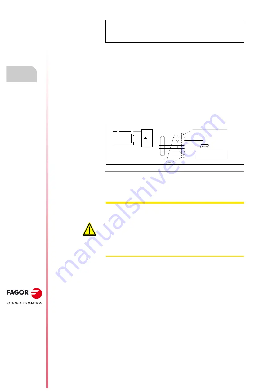
A transformer-rectifier circuit as the one shown in figure
enough to supply the brake of an FXM servomotor.
See detailed in section,
10.16 Holding brake connection diagram
of
chapter
10. CONNECTION DIAGRAMS
of the “man_dds_hard.pdf”
manual.
Note.
Note that for servomotors with an MC-80 plug, the pin names are
different: U phase (pin C), V phase (pin H), W phase (pin G) and PE (pin
B). When using a brake, pin A will be supplied with 24 Vdc and pin E
with 0 Vdc.
F- 2/8
Holding brake connection diagram.
9$&
+ROGLQJEUDNHRSWLRQ
95HOHDVHG
9+ROGLQJ
);002725
32:(5&211(&725
03&[[LQPPð
&DEOHZLWKRXWFRQQHFWRUV
9'&
(
)
'
WARNING.
Voltage between 22-26 Vdc release the shaft. Make sure that no voltage
over 26 V is applied that prevents the shaft from turning.
When installing the servomotor, make sure that the brake fully releases
the shaft before making it turn for the first time.
The 24 Vdc generated by modules like PS-25B4, APS-24, XPS or
another power supply handle the drive control signals and must never be
used to control the brake. These brakes generate voltage peaks that
could damage the drive.


