FAE VRTMT 8 Manual Download Page 4


!


CAUTION!  BEFORE  INSTALLING  THE 

VRTMT

  CONTROLLER  READ  CAREFULLY  THE  MANUAL  AND 

FOLLOW  ALL  THE  INSTRUCTIONS  HEREIN.  WITH  POWERED  CONTROLLER  DO  NOT  TOUCH  THE 

INNER  ELECTRICAL  PARTS  IN  ANY  CASE.  IN  COMPLIANCE  WITH  THE  EU  RULES  AND  THE  EMC 

DIRECTIVES, PLEASE  REMIND THAT THE  VRTMT CONTROLLER IS DESIGNED TO  BE INCORPORATED 

ON MACHINES OR INTEGRATED ON CONTROL PANELS AND THEREFORE IS TO BE CONSIDERED AS A 

COMPONENT  FOR  PROFESSIONAL  USE.  THE  MACHINE  INSTALLATOR  SHALL  PROVIDE  FOR  THE  GUARANTEE    OF 

COMPLIANCE  OF  ITS  EQUIPMENT  TO  SUCH  RULES.  IN  THE  EVENT  THAT  THE  CONTROLLER  FAILS  TO  OPERATE  AND 

CAUSES  DAMAGES  TO  THINGS  OR  PERSONS  IT  SHALL  BE  THE  INSTALLER’S  RESPONSIBILITY  TO  PROVIDE  SAFETY 

DEVICES  OR  SYSTEMS  TO  PROTECT  OR  WARN  ABOUT  THE  FAILED  OPERATION.  IN  ANY  MOMENT  AND  WITHOUT 

NOTICE  FAE  FAGAN  APPLICAZIONI  ELETTRONICHE  RESERVES  TO  CARRY  OUT  TECHNICAL  CHANGES  AIMED  AT 

ENHANCING THE QUALITY OR THE PERFORMANCE OF ITS PRODUCTS. 


PRELIMINARY INSPECTIONS - WARRANTY 


Before installing the controller, make sure that it has not been damaged during the carrying and that it corresponds 

to  the  model  ordered.  Check  that  the  technical  specifications  listed  in  the  label  match  with  those  written  in  the 

delivery note and in the order form. The controller is covered by a 12-month warranty starting from the delivery. The 

warranty  covers  production  defects  not  due  to  damaging  or  wrong  use,  for  goods  returned  to  us  EX-WORKS.  Any 

damage occurred during the carrying shall be reported to the carrier in with the local legislation. 

DISPOSAL 

The sign marked on the equipment indicates that it is not to be considered as a normal domestic waste, therefore it 

has to be disposed of in a specific electrical and electronic equipment recycling point. 


SERIAL NUMBER

   _________ /_______                


SOFTWARE VERS.

   ________ 


VRTMT – USE FEATURES 


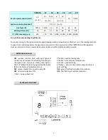
The VRTMT electronic controller is normally used to control the speed of AC fans, pumps and centrifugal pumps. It is 

based  on  the  principle  of  symmetrical  phase  partialisation  and  It  is  suitable  for  adjustable  voltage  motors.  VRTMT 

operates  on  the  basis  of  the  inputs  received  through  the  measurements,  the  parameters  settings  values,  the 

controlling  I/O  and  the  control  panel.  The  control  panel  is  used  to  set  the  parameters  values  and  read  the 

information about the unit status. VRTMT is provided with Modbus connection to dialog with a supervising remote 

device.  


Summary of Contents for VRTMT 8

Page 1: ...VRTMT CONTROLLER FOR AC FANS User s manual version 03 16 FAE Fagan Applicazioni Elettroniche www faefagan it...

Page 2: ...pin between two parentheses indicating the possibility of change 6 Click on the button increasing the number of pins up to 0023 Then confirm with the key 7 Keyboard It now says BASIC SETTINGS Confirm...

Page 3: ...R 12 Heating Cycle Parameters HEA CHILLER 13 OPERATING PARAMETERS MENU DRY COOLER 15 Parameters Reading and Editing 15 Cooling Cycle Parameters CO1 DRY COOLER 16 Heating Cycle Parameters HEA DRY COOLE...

Page 4: ...the model ordered Check that the technical specifications listed in the label match with those written in the delivery note and in the order form The controller is covered by a 12 month warranty start...

Page 5: ...ON Class II at the command imputs insulation of 4kV between commands block and the device supplied parts Class I as regards the accessible parts PROTECTIONS Phase lost inside overheating sensor missin...

Page 6: ...sun s rays Make sure that it does not undergo vibrations Cable glands IP68 Metric Model Weight kG Dimensions mm A B C Fixed screw mm D E F M16 M20 M25 M32 M40 VRTMT 8 2 5 230 165 150 215 80 M4 1 1 2...

Page 7: ...lar working also cold temperature it is recommended you insure a constant power supply avoiding turning it off continually All connections wires must resist to a 80 C working temperature Avoid routing...

Page 8: ...of the VRTMS50 and 60 regulators must be crimped to form an eyelet M6 hole and the nuts E10 tightened with a wrench LED WARNING SIGNALS DL1 yellow starts to flash with input signal at minimum and inc...

Page 9: ...7...

Page 10: ...sic sett menu 22 0V Ground I O Mass for the digital inputs 0 10 Analog input type 0 10V Ri 40k 0 10V command for mode slave running 22 V 12V power supply output max 30mA 4 20mA pressure transducer pow...

Page 11: ...m CO COOL or HEA HEAT followed by the number 1 or 2 for first or second cycle In this mode Press the key to slide the state menu downward Press the key to slide the state menu upward STATE WINDOW BOXE...

Page 12: ...tal commands I1 I2 I3 I4 are not active Defines the state of the relay 1 relay 2 and relay 3 The asterisk means that they are powered and the contacts NO and COM are eachother closed The instructions...

Page 13: ...d the corresponding identifying code The second line of the display is dotted Press the key to access the parameters of the visualized menu Press the key to return to the state menu Press the key to g...

Page 14: ...point Min P1 Max P_MAX Def 24 bar Maximum production pressure above this the output is at the voltage MotorMaxLim Min P2 Max Full Scale Def 25 bar Voltage speed of the pressure point P1 Min MotorMinL...

Page 15: ...ed V2 point Min P_MAX Max P2 Def 7 bar Pressure of the voltage speed V1 point Min P1 Max Full Scale Def 11 bar Maximum production pressure below this the output is at the voltage MotorMaxLim Min 0 bar...

Page 16: ...14...

Page 17: ...next menu Press the key to return to the previous menu PARAMETERS READING AND EDITING The parameters windows display the name of the parameter the identifying code of the corresponding menu the value...

Page 18: ...int Min T1 Max T_MAX Def 28 0 C Maximum production temperature above this the output is at the voltage MotorMaxLim Min T2 Max 95 C Def 29 0 C Voltage speed of the temperature point T1 Min MotorMinLim...

Page 19: ...t Min T_MAX Max T2 Def 22 0 C Temperature of the voltage V1 speed point Min T1 Max 95 C Def 24 0 C Maximum production temperature over this the output is at the voltage MotorMaxLim Min 0 C Max T1 Def...

Page 20: ...o to the next menu Press the key to return to the previous menu PARAMETERS READING AND EDITING The parameters windows display the name of the parameter the identifying code of the corresponding menu t...

Page 21: ...Def 13 Control signal of the Voltage V2 speed point Min InMin Max 100 Def 95 Voltage speed of signal command IN MINIM Min MotorMinLim Max V2 Def 20 Voltage speed of signal command IN MAX Min V1 Max Mo...

Page 22: ...if the pressure temperature is lower than P1 T1 the Voltage OUT Vout will be fixed at the value of the V1 Limit see for example the below chart 2 HEAT cycle For V1 Limit V1 of the active cycle if the...

Page 23: ...mpRZM_20 0 5 4 5V 0 20 7 bar 8 bar 12 bar 13 bar 4 bar 6 bar 3 bar MPRZM_34 0 5 4 5V 0 34 5 bar 13 bar 18 bar 19 bar 4 bar 6 bar 3 bar MPRZM_45 0 5 4 5V 0 45 bar 20 bar 24 bar 25 bar 7 bar 11 bar 5 ba...

Page 24: ...iloPascal Caution numbers won t be converted Adjusting value of the temperature probe connected to input 1 Min 5 C Max 5 C Def 0 C WITH S1 CARD Adjusting value of the temperature probe connected to in...

Page 25: ...on demand Caution the controller will be restart and the output voltage will be increased gradually up to the 100 to return to the basic setting value The whole process will be automatic and last few...

Page 26: ...Lim max relay value and disabled under the Lim min relay value The Lim max parameters and lim min are expressed in C or bar depending on the setting They are displayed only when relay is set to hyste...

Page 27: ...t can go from 1 to 247 Def 1 Defines the transmission speed on channel RS 485 Possible modes 9600bps 19200bps Def 38400bps Defines the type of parity on the serial transmission Possibles modes None De...

Page 28: ...ad at maximum speed with a pressure of P2 1bar If the ambient temperature drops to 5 C the bandwidth increases by 4x0 25x2 2bar then at ambient temperature of 5 C the control will command the load at...

Page 29: ...rage With low battery the display visualizes b Displays the date and time of the internal clock To change press In this menu a weekly calendar can be enabled to edit the setting mode by activating the...

Reviews: