background image

27

EN

SLICER CLEANING

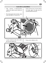
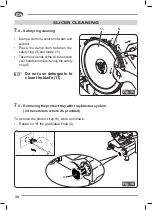
•  Fully unscrew (counterclockwise 

rotation) the blade guard locking tie 

rod  (17);

•  If the blade guard (9) is blocked, press 

on the rod knob (17) to move it;

•  Remove the tie rod (17) and remove 

the blade guard (9) using only the 

special lateral knobs (23);

•  Loosen and remove the two screws 

with knurled head (24);

•  Remove the deflector (25).

24

24

25

23

23

11

9

17

26

4

5

6

7

8

3

2

EN

SLICER CLEANING


The machines have to be carefully cleaned at least once a day; if it is 

necessary more frequently. After a shorter or longer period of inactivity 

clean the slicer before use.


WARNING: Cutting hazard! 

  Use protective cut- and tear-resistant gloves and perform 

  all operations with extreme care. 


PAY ATTENTION AT ALL TIMES! 

7

.1  - Disassembling the machine for cleaning

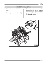
•  Disconnect the plug from the mains power supply.;

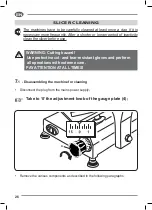
Take to ‘0’ the adjustment knob of the gauge plate (4);

•  Remove the various components as described in the following paragraphs;

4

Summary of Contents for S220

Page 1: ...l 39 0331 212252 Fax 39 0331 216443 www slicers it info slicers it 100 Made in Italy F 195 S 220 F 250 ES S 220 AF F 250 E F 250 I F 275 E F 275 I F 275 IL F 300 R F 300 E F 300 EL F 300 CL F 300 I F...

Page 2: ......

Page 3: ...l 39 0331 212252 Fax 39 0331 216443 www slicers it info slicers it 100 Made in Italy F 195 S 220 F 250 ES S 220 AF F 250 E F 250 I F 275 E F 275 I F 275 IL F 300 R F 300 E F 300 EL F 300 CL F 300 I F...

Page 4: ......

Page 5: ...ES Pag 16 SPACE REQUIREMENT Pag 17 MAIN TECHNICAL DATA Pag 17 MAIN COMPONENTS Pag 20 INSTALLATION ADN PRELIMINARY CHECKS Pag 22 COMMANDS DESCRIPTION Pag 23 USING THE MACHINE Pag 23 SLICER CLEANING Pag...

Page 6: ...equipment It also alerts the user on incorrect operating modes Safety warnings indispensable before use Carefully read the warnings contained herein as they provide important information regarding sa...

Page 7: ...dults adequately trained for the purpose who have carefully red the content of this manual The elements of the packing plasti bags expanded polystyrene etc must be kept out of reach of children as the...

Page 8: ...d by the appliance In general it is not advisable to use adapters multiple sockets and or extensions Do not connect the appliance to the electrical power through external timers or remote operating sy...

Page 9: ...e under a socket so that the wire doesn t interfere with the correct use of the machine Do not leave the appliance plugged in unnecessarily Unplug it from the power supply when the device is not used...

Page 10: ...in water Do not use the appliance in environments containing explosive combustible gases or flammable liquids paints glues spray cans etc DANGER OF EXPLOSION AND FIRE This device is intended for dome...

Page 11: ...n if its life had not come to an end IIf you have any doubts regarding the contents of the user guide or require additional information please contact the manufacturer or technical support immediately...

Page 12: ...at is extraneous to normal slicing operations Place and remove the goods to be sliced on the sliding plate only with the platter completely retracted away from the blade and the cart totally towards t...

Page 13: ...not responsible directly and indirectly for any damage caused by improper use of the device resulting from failure to follow instructions contained in this manual use of untrained personnel use not in...

Page 14: ...anza alle norme del Country of use PACKING This product complied with Directive 2012 19 UE The crossed out wheeled bin symbol on equipment indicates that it must be treated separately from household w...

Page 15: ...EPLATES CONFORMITY MARKINGS The device described in this manual is produced in accordance with the directives in force as amended All component parts are adapted to the requirements of the Directive a...

Page 16: ...riven by an electric motor which has the function of slicing food products and by a carriage sliding on rails which on its turn supports a carriage plate parallel to the blade The slice thickness is a...

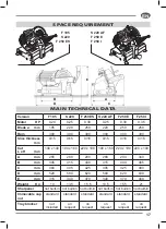
Page 17: ...d to slice food of the type and within the dimensional limits indicated in this instruction manuals 2 3 a Intended use sliceable products The following products may be sliced All types of cold cuts ra...

Page 18: ...fety devices installed on the equipment 3 1 Residual risks During slicer use cleaning and maintenance operations notwithstanding all the possible cautions taken during the design and the construction...

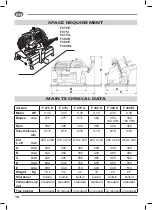
Page 19: ...40 x 140 190 x 160 220 x 190 190 x 160 220 x 190 220 x 190 A mm 255 280 290 280 290 340 B mm 345 415 440 415 440 465 C mm 360 405 425 405 425 480 D mm 520 580 620 580 620 630 E mm 315 340 370 340 370...

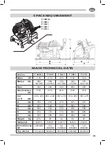
Page 20: ...m 0 16 0 16 0 16 0 16 0 16 0 16 Cut L x H mm 220 x 220 210 x 210 230 x 215 220 x 210 220 x 220 260 x 230 A mm 290 340 340 290 340 340 B mm 440 465 490 440 465 490 C mm 440 495 500 485 495 500 D mm 620...

Page 21: ...260 260 Slice thickness mm 0 16 0 16 0 16 0 16 0 16 Cut L x H mm 300 x 220 260 x 220 260 x 235 310 x 260 300 x 275 A mm 350 410 410 415 415 B mm 570 530 530 580 580 C mm 560 540 550 585 585 D mm 870...

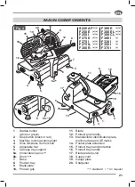
Page 22: ...tray support 6a Immovable cap nut x 7 Base 8 Product tray 9 Blade plate 10 Product grip 11 Blade 12 Product grip handle 13 Manufacturer identification plate machine data and UE marks 14 Pusher plate e...

Page 23: ...thickness control knob 5 Adjustable foot 6 Carriage tray support 6a Immovable cap nut x 6b Knob y z 7 Base 8 Product tray 9 Blade plate 10 Product grip 11 Blade 12 Product grip handle 13 Manufacturer...

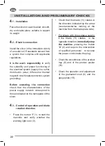
Page 24: ...pply network correspond to those indicated on the nameplate of the slicer 4 3 Control of operation and blade rotation direction Press the button I 1 to start the machine and verify whether the warning...

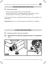
Page 25: ...es that the machine works correctly Press the black or red button 2 to stop the blade movement The thickness of the slices is adjustable rotating the knob 4 with graduated scale anticlockwise Regulati...

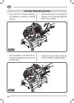
Page 26: ...position USING THE MACHINE Lift the product grip 10 by pulling it away by 10 cm from the blade and put it in rest position Lay the product to be sliced on the carriage 8 against the wall on the operat...

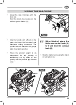
Page 27: ...and start the forwward and backward cutting movement The product travels towards the gauge plate by weight gravity When the product weight or its dimensions do not provide a satisfactory cut by effec...

Page 28: ...lean the slicer before use WARNING Cutting hazard Use protective cut and tear resistant gloves and perform all operations with extreme care PAY ATTENTION AT ALL TIMES 7 1 Disassembling the machine for...

Page 29: ...locking tie rod 17 If the blade guard 9 is blocked press on the rod knob 17 to move it Remove the tie rod 17 and remove the blade guard 9 using only the special lateral knobs 23 Loosen and remove the...

Page 30: ...move it by lifting it For the machine s body and blade cleaning use only a cloth dampened in water or alcohol and a biodegradable frothy dishwasher cleanser at pH 7 8 at a temperature at least of 30 C...

Page 31: ...for the sharp zones of the product tray 8 and of the product grip 10 Rinse only with hot water and dry with soft and spongy cloths DO NOT clean the machine with water jets with vapor similar methods...

Page 32: ...fety ring S and blade 11 Take the two ends of the cloth between your hands and slide it along the safety ring S Do not use detergents to clean the blade 11 7 5 Removing the product tray with tray bloc...

Page 33: ...tray next to the graduated knob Completely unscrew the knob 6b Strongly pull the tray towards the operator until you hear the coupling click safety pivot In this position the gauge plate 19 and the p...

Page 34: ...To reassemble it Correctly reposition the tray 8 on the tray support 6 Tighten the knob 6b until you free the tray 8 7 7 Store the slicer Whenyoufinishusingit after carefully have cleaned all the comp...

Page 35: ...product grip sliding bar weekly Visual check of the power cord and of the gland on the machine s base conditions periodically The maintenance operations must be performed always after disconnecting t...

Page 36: ...bag container provided unscrew the knurled knob of the sharpener and insert the threaded metallic pin into the hole 4a specially crafted on the product carriage so that the two emery wheels vare towar...

Page 37: ...the switch to stop it checking with a slight shift using a pencil to the outside of the blade if the burr is formed We reccomend to perform this check very carefully as the blade is very sharp Ascerta...

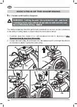
Page 38: ...lade sharpening should be performed periodically as soon as you feel a decrease in the ability of cutting blade it should follow the instructions below 1 Carefully clean the blade 11 c with denatured...

Page 39: ...with a slight shift using a pencil to the outside of the blade if the burr is formed We reccomend to perform this check very carefully as the blade is very sharp 5 Ascertained the formation of the bur...

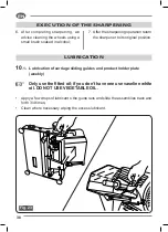
Page 40: ...operation return the sharpener to its original position 10 1 Lubrication of carriage sliding guides and product holder plate weekly Only use the fitted oil if you don t have one use vaseline white oil...

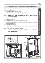
Page 41: ...orce and the belt may be damaged Only for personnel authorized by the manufacturer 30 32 31 5 33 34 39 Fig 24 EN MOTOR BELT TENSION ADJUSTMENT When after a given time the slicer has an unusual noise b...

Page 42: ...ployed When demolishing without outside assistance sort the various types of material and hand over to authorised businesses for disposal ALWAYS comply with the current legislation of the country in w...

Page 43: ...fied personnel TROUBLESHOOTING The following information is intended to aid in identifying and correcting defects and faults that may occur during use of the machine Some failures can be resolved by t...

Page 44: ...ne starts but vibrates the motor is very hot and there is bad smell Defective motor or transmission Do not use the machine consult promptly the customer service The machine under load slows or stops D...

Page 45: ...the manufacturer ELECTRICAL SCHEME TG 03SE for versions F 195 S 220 F 250 ES S 220 AF F 250 E F 275 E F 300 R CONDENSER tighten on slicer s chassis y e l l o w g r e e n brown b l u e POWER 220V 50Hz...

Page 46: ...versions F 250 I F 275 I F 275 IL F 300 E F 300 EL F 300 CL F 300 I F 330 I F 350 I F 370 I N B In versions F300I F330I F350I F370I n 2 condensers of 6 3 F CONDENSER tighten on slicer s chassis y e l...

Page 47: ...manufacturer ELECTRICAL SCHEME THREE PHASE TG00SR all versions Black Black Green Motor Line Yellow Red Brown Blue Black Brown Blue Black Brown Brown Blue Blue tighten on slicer s chassis CONNECTION A...

Page 48: ...46 EN PAGE INTENTIONALLY LEFT BLANK 1 6 7 8 9 10 11 12 13 16 15 17 18 19 163 164 165 166 167 168 169 169 170 170 171 172 173 174 4 175 176 178...

Page 49: ...121 122 123 124 125 126 127 129 130 133 116 135 136 133 138 139 140 141 140 141 142 143 144 146 147 148 149 151 155 156 157 158 159 160 3 5 154 68 69 98 111 68 69 70 71 72 82 83 84 85 86 84 87 88 89...

Page 50: ...48 EN...

Page 51: ...F195 S220 F250ES F300R F195AF S220AF F250E F275E Ed 06 2016 49 F195 S220 F250ES F300R F195AF S220AF F250E F275E Ed 06 2016 EN...

Page 52: ...50 EN...

Page 53: ...F250I F275I F300E F275IL F300EL Ed 06 2016 51 F250I F275I F300E F275IL F300EL Ed 06 2016 EN...

Page 54: ...52 EN...

Page 55: ...Ed 06 2016 53 Ed 06 2016 EN...

Page 56: ...54 128 127 1 12 121 122 125 123 124 126 EN 125 123 124...

Page 57: ...128 127 Ed 06 2016 116 118 117 119 120 121 22 126 128 127 60 113 114 115 55 128 127 Ed 06 2016 116 118 117 119 120 121 122 125 123 124 126 128 127 60 113 114 115 EN...

Page 58: ...56 127 126 122 125 123 124 121 90 EN 125 123 124...

Page 59: ...Ed 06 2016 116 127 127 115 114 113 65 6 126 118 122 121 90 120 119 117 57 Ed 06 2016 116 127 127 115 114 113 65 126 126 118 122 125 123 124 121 90 120 119 117 EN...

Page 60: ...0R F300E F300EL F300CL 125 127 25 126 131 132 133 135 136 137 138 114 65 113 115 139 138 137 116 117 118 120 121 122 92 24 123 126 128 124 119 134 130 129 Solo per Only for Seulement pour Nur f r S lo...

Page 61: ...ter from 195 to 250 mm CE professional AISI 420 100Cr6 models with blade diameter from 300 to 370 mm CE professional FOODSTUFF SUITABILITY TEST The material respects the overall migration and specific...

Page 62: ...03 1973 or on the basis of the calculations carried out considering the content of the substances subjected to migration limits The calculations were made assuming that 1 kg foodstuff comes into cont...

Page 63: ...a suitable temperature extraction of the head space via 30 minute contact at 125 C and gas chromatographic analysis with mass detector Screening of semi volatile organic and non volatile compounds in...

Page 64: ...Presidential Decree 777 82 and as amended 2 The blade of the afore mentioned slicer is manufactured with the following alloy AISI 420 C45 _ All domestic CE models and models with blade diameter from...

Page 65: ...ns carried out considering the content of the substances subjected to migration limits The calculations were made assuming that 1 kg foodstuff comes into contact with 1 product The material contains s...

Page 66: ...itable temperature extraction of the head space via 30 minute contact at 125 C and gas chromatographic analysis with mass detector Conclusions No hazardous substances have been detected Screening of s...

Page 67: ...Notes...

Page 68: ......

Page 69: ...03 2019...

Page 70: ...39 0331 212252 Fax 39 0331 216443 www slicers it info slicers it 100 Made in Italy F 195 S 220 F 250 ES S 220 AF F 250 E F 250 I F 275 E F 275 I F 275 IL F 300 R F 300 E F 300 EL F 300 CL F 300 I F 33...

Reviews: