background image

FabiaTech Corporation 

¾


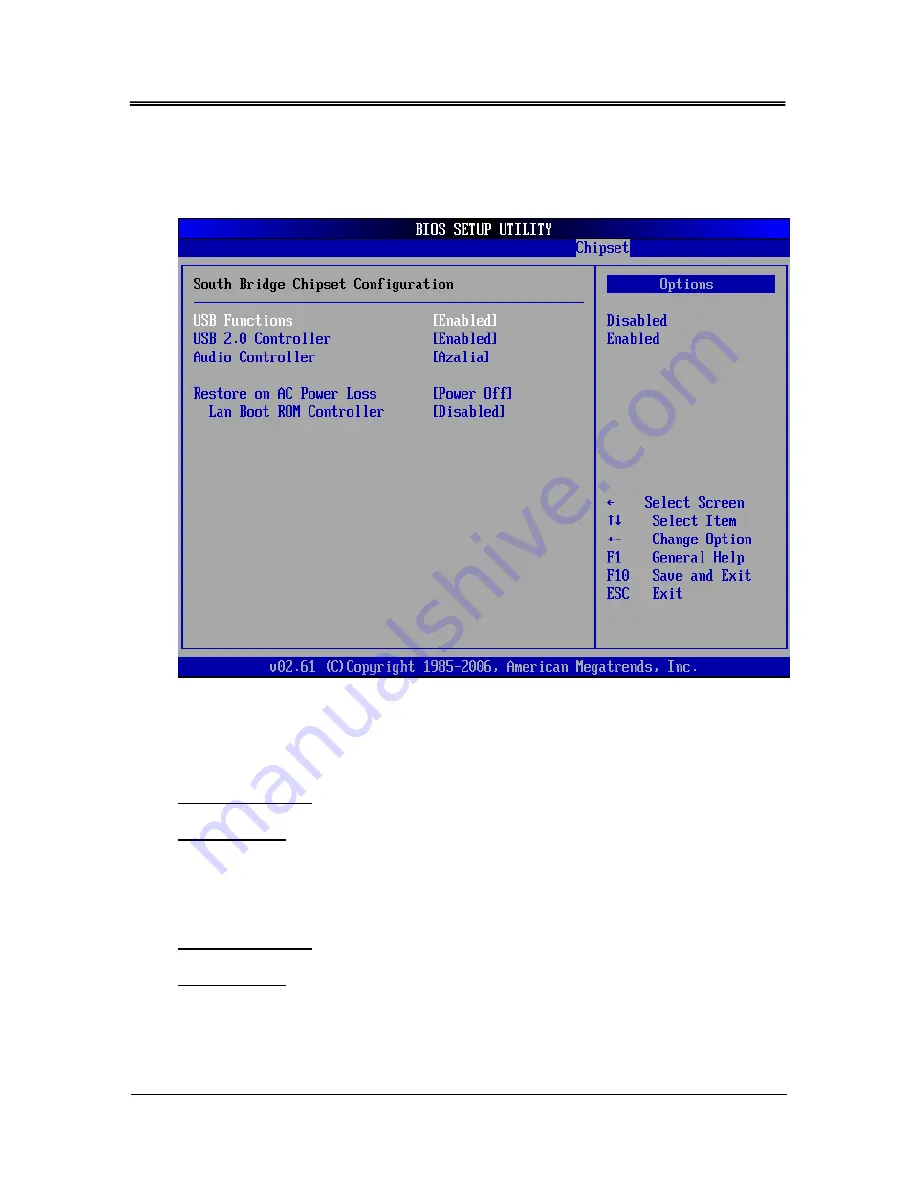
South Bridge Configuration 

You can use this screen to select options for the South Bridge Configuration. South 
Bridge is a chipset on the motherboard that controls the basic I/O functions, LAN 

port, and audio function. 


USB Function 

Select Enabled, if a USB device is installed to the system.  If Disabled are selected, 
the system will not be able to use a USB device. 

Available Options: Disabled, and Enabled 

Default setting: Enabled 

USB 2.0 Controller 

This field is select Enabled or Disabled the USB 2.0 controllers  

Available Options: Disabled, Enabled 

Default setting: Enabled  


49 

Summary of Contents for FP8082 Series

Page 1: ...FabiaTech Corporation IPC Solution Website http www fabiatech com Email support fabiatech com Panel PC FP8082 Series User s Manual JUL 2013 Version 1 1 Part Number FP8082 ...

Page 2: ...shing performance or use of this document Trademarks Trademarks brand names and products names mentioned in this publication are used for identification purpose only and are the properties of their respective owners Technical Support If you have problems or difficulties in using the system or setting up the relevant devices and software that are not explained in this manual please contact our serv...

Page 3: ...ectors Panel 14 Connecting the DC Power and Power Button 17 Chapter 3 BIOS Setup 19 Overview 19 BIOS Functions 20 Keyboard Convention 21 Main Setup 22 Advanced Setup 23 CPU Configuration 23 IDE Configuration 24 SuperIO Chipset Configuration Win627 Super IO Chipset 27 Hardware Health Configuration 30 Advanced ACPI Settings 31 APM Configuration 33 USB Configuration 35 PCIPnP Setup 37 Boot Setup 39 B...

Page 4: ...000 XP 53 BIOS Flash Utility 53 Watchdog Timer 54 Watchdog Timer Setting 55 Watchdog Timer Enabled 56 Watchdog Timer Trigger 56 Watchdog Timer Disabled 57 Programming RS 485 58 Send out one character Transmit 59 Send out one block data Transmit the data more than two characters 59 Receive data 59 Basic Language Example 59 Chapter 5 Technical Reference 61 Trouble Shooting 61 Post Beep and Error Mes...

Page 5: ...CMOS RAM Map 67 Serial Ports 68 Appendix 72 Dimension 72 v ...

Page 6: ...vi ...

Page 7: ...sor Able to support 1 6 GHz CPU this system supports one 10 100 1000M Base TX LAN ports 1 So DIMM socket supports up to 2GB DDR2 RAM PCIe mini card socket for wireless LAN six USB2 0 ports audio and a dual display VGA controller Each FP8082 has six ports for I O communication One RS232 RS422 RS485 port and five RS232 ports are available The FP8082is perfect for ATM machines KIOSK point of sales po...

Page 8: ...s Audio Ear Phone And MIC In RJ45 LAN port One PCIE RTL8111C 10 100 1000Mbps PCIe Mini Card Socket One Panel Display Type 8 4 TFT LED LCD Max Resolution 800X600 Max Colors 262K RGB 6 Bit Luminance cd 450 cd Dot Size mm 0 213 0 213 Viewing Angle H V 160 140 Lamp Life 50 000Hrs Touch Screen w T 4 Wire Analog Resistive Resolution 800X600 Light Transmission 80 5 Life Time 10 Million Activations Operat...

Page 9: ...FabiaTech Corporation 3 Layout USB CF MIC EAR PHONE COM5 CRT COM1 USB LAN COM2 COM3 COM4 DC IN KB MOUSE RESET POWER BUTTON COM6 Antenna Antenna 3 2 1 6 5 4 DC12 24V CF Antenna FP8082 ...

Page 10: ...et modules especially for WLAN GPRS module One DC In plug connector and one terminal block for DC power input One power push button and one reset button Storage Bay Compact Flash socket for Compact Flash modules or MicroDrives One 2 5 SATA hard disk space LCD Display Front panel with 8 4 inch color LVDS TFT LED LCD panel Supports up to SVGA 800X600 64K colors Resistive Touch screen Only For FP8082...

Page 11: ...FabiaTech Corporation Power requirement 12V 24V DC 2 6A Maximum 1 36A typical with DC19V Input Dimensions 60 0mm D x 250 0mm W x 180 0mm H 5 ...

Page 12: ...install the FP8082 it is recommended that you keep the diskette or CD that contains drivers and document files and keep the document copies or unused cables in the carton for future use The following lists the accessories that may be included in your FP8082package Some accessories are optional items that are only shipped upon order One FP8082x industrial Panel PC One AC to DC19V power adapter and ...

Page 13: ...r switch to off and unplug AC cable 2 Install or unplug any connector PCIe mini card Compact Flash and hard disk be sure that the power is disconnected or power switch to off from the system If not this may damage the system 3 The ESD Electricity Static Discharge may be created from human body that touches the board It may do damage to the board circuit 4 When using the screwdriver on screws befor...

Page 14: ...A HDD inside PCIe mini card module DDR2 RAM module to the FP8082 and how to install the FP8082 fixers Please see the spots circled a Unscrew Right Side Cover Installing Compact b Unscrew and Separate the Covers The following figure will guide you separate the FP8082 covers then installing hardware devices b1 Unscrews the Back Side Cover Note The Compact Flash socket supports 3 3V Compact Flash and...

Page 15: ... the Right Side Metal Frame b3 Unscrews the Bottom Side I O Metal Frame b4 Unscrews and Separate the Main Board PAD 2t PAD 3t Caution Please do not touch the surface of thermal pads and avoid removing them from chipset M3X3 M3X3 X14 M3X5 ...

Page 16: ...See as following figure and rear pictures The So DIMM socket supports 1GB to 2GB of DDR2 400 533 RAM modules Note 1 Remove the inverter board before installing hard disk 2 Use caution when handling the hard disk to prevent damage to SATA connector as you inserted hard disk Be careful with the orientation when installing connectors M3X2 10 ...

Page 17: ... auxiliary board e1 Installing PCIe Mini Card and SIM card M2X2 Note 1 When installing PCIe GPRS Mini card on FP8082 system these is need the installing the SIM Card to system board 2 Open the cover with SIM socket then insert SIM card into the SIM card hold Make sure that the SIM card is properly inserted and that golden contact area on the card is facing downwards e2 Installing Half Size Mini PC...

Page 18: ...sal fixers on FP8082 Please refer to the back side figure for installing the FP8082with universal fixers f1 FP8082 Panel Mounting Kit with VESA 75 100 mm Standards f2 Embedded Wall mounting Step 1 Step 2 Cut out dimension 222 x 151 mm WALL M4X4 M3X4 ...

Page 19: ...FabiaTech Corporation f3 FP8081K1 DIN RAIL mounting kit M3X6 13 ...

Page 20: ...cting the monitor keyboard mouse LAN audio COM and USB to the FP8082 See following figure and a side pictures a Bottom Side of FP8082Panel PC COM5 CRT LAN COM1 USB COM2 COM3 COM4 DC IN KB MOUSE RESET POWER BUTTON COM6 2 3 1 4 5 6 DC12 24V b Right Side of FP8082 Panel PC MIC USB CF EAR PHONE Antenna CF Antenna ...

Page 21: ...able If PS 2 keyboard and mouse will be used simultaneously a Y type 3 terminal adapter cable is needed KB Mouse Description 1 Keyboard Data 2 Mouse Data 3 Ground 4 VCC 5 Keyboard Clock 6 Mouse Clock 3 Connecting the COM ports The DB9 COM1 COM6 is standard serials port connector The COM1 are designed for multiple proposes use BIOS Setup of the CPU board selects RS 232 or RS 485 of these COM The fo...

Page 22: ...pports a four port USB connector Any USB device can be attached to USB ports with plug and play supported The right side ports is USB 5 6 and the bottom side ports is USB 1 2 and 3 4 6 Connecting the Audio Microphone In EAR phone RJ45 LAN1 2 RJ45 LAN1 2 1 TPTX 5 TPTX1 2 TPTX 6 TPRX 3 TPRX 7 TPRX1 4 TPTX1 8 TPRX1 USB Signal 1 USBV 2 USBD 3 USBD 4 USBG RJ45 connector Front View 4 1 The following lis...

Page 23: ...o fix hole 1 then pull at cable 3 DC Power Connector Use external 2 pin apart able terminal block Power Button Reset Push Button Pushing the Power button once will switch the FP8082on and off depending on system BIOS Advanced Power Manager Power Button Mode or Chipset South Bridge Configuration Restore On AC Power Lose And Reset push button is switcher for system reset Push and release the button ...

Page 24: ...FabiaTech Corporation 18 ...

Page 25: ... firmware that interacts directly with the hardware components and facilitates interaction between the system hardware and the operating system The BIOS default values ensure that the system will function at its normal capability In the worst situation the user may have corrupted the original settings set by the manufacturer All the changes you make will be saved in the system RAM and will not be ...

Page 26: ...ion IDE Configuration SuperIO Configuration Hardware Health Configuration ACPI APM Configuration USB Configuration 3 PCIPnP 4 Boot Boot Settings Configuration Boot Device Priority Hard Disk Drives CD DVD Drivers 5 Security Change Supervisor Password Change User Password Clear User Password Boot Sector Virus Protection 20 ...

Page 27: ... system according to optimal setting with pre defined values This is also the factory default setting of the system when you receive the board Load Fail Safe Default to configure the system in fail safe mode with predefined values Keyboard Convention On the BIOS the following keys can be used to operate and manage the menu Item Function ESC To exit the current menu or message Page Up Page Down To ...

Page 28: ... determined by POST Power On Self Test of the BIOS System Date Time Setup Highlight the Date field and then press the Page Up Page Down or keys to set the current date Follow the month day and year format Highlight the Time field and then press the Page Up Page Down or keys to set the current date Follow the hour minute and second format The user can bypass the date and time prompts by creating an...

Page 29: ...ption by highlighting it using the Arrow keys All Advanced BIOS Setup options are described in this section The Advanced BIOS Setup screen is shown below The sub menus are described on the following pages CPU Configuration You can use this screen to select options for the CPU information Use the up and down Arrow keys to select an item Use the Plus and Minus keys to change the value of the selecte...

Page 30: ...n is shown below ATA IDE Configuration This item specifies the ATA IDE channels used by the onboard PATA SATA IDE controller depend on the operation system OS that installed When installed DOS WIN95 98 ME Will can set to compatible mode And set to Enhanced mode if you are using native OS like Windows XP 2k Available Options Disabled Compatible and Enhanced Default setting Compatible Legacy IDE Cha...

Page 31: ...he power off and then power on without having to reconfigure your hard drive type If you use older hard disk drives which do not support this feature then you must configure the hard disk drive in the standard method as described above by the USER option PIO MODE PIO means Programmed Input Output Rather than have the BIOS issue a series of commands to affect a transfer to or from the disk drive PI...

Page 32: ...ine tune the settings to allow for faster boot times Adjust this setting until a suitable timing that can detect all IDE disk drives attached is found Available Options 0 5 10 15 20 25 30 and 35 Default setting 35 ATA PI 80 Pin Cable Detection Set this option to select the method used to detect the ATA PI 80 pin cable The use of an 80 conductor ATA cable is mandatory for running Ultra ATA 66 Ultra...

Page 33: ...MHz 16MHz Controller Available Options 6MHz 8MHz 12MHz and 16MHz Default setting 12MHz Serial Port 1 Address These fields select the I O port address for each Serial port Available Options Disabled 2F8H IRQ3 3E8H IRQ4 and 2E8H IRQ3 Default setting 3F8H IRQ4 Serial Port1 Mode Selection These fields item can select RS 232 RS 422 and RS 485 of select port 1 Available Options RS 232 RS 422 and RS485 D...

Page 34: ...g 3E8H Serial Port3 IRQ These fields item can select the IRQ of Serial port 3 Available Options 10 and 11 Default setting 11 Serial Port 4 Address These fields select the I O port address for each Serial port Available Options Disabled 3E8 and 2E8 Default setting 2E8H Serial Port4 IRQ These fields item can select the IRQ of Serial port 4 Available Options 10 and 11 Default setting 10 Serial Port 5...

Page 35: ...e Options 10 and 11 Default setting 11 Serial Port 6 Address These fields select the I O port address for each Serial port Available Options Disabled 3E0 and 2E0 Default setting 2E0H Serial Port6 IRQ These fields item can select the IRQ of Serial port 6 Available Options 10 and 11 Default setting 10 29 ...

Page 36: ...FabiaTech Corporation Hardware Health Configuration On the Hardware Monitor Setup screen you can monitor the system temperature CPU voltage and VCC voltage 30 ...

Page 37: ...le Options Yes and No Default setting Yes Advanced ACPI Configuration ACPI Version Feature Set this value to allow or prevent the system to be complaint with the ACPI Specification Available Options ACPIv1 0 ACPIv2 0 and ACPIv3 0 Default setting ACPIv1 0 AMI OEMB Table Set this value to allow the ACPI BIOS to add a pointer to an OEMB table in the Root System Description Table RSDT table 31 ...

Page 38: ...tting Enabled Chipset ACPI Configuration APIC ACPI SCI IRQ Allows you to enable or disable the internal I O APIC and Multiprocessor Tables Disable the APIC ACPI SCI IRQ may require the O S to be reinstalled Available Options Disabled and Enabled Default setting Disabled 32 ...

Page 39: ...s Disabled and Enabled Default setting Enabled Video Power Down Mode This field specifies the power conserving state that video subsystem enters after the specified period of display inactivity has expired Available Options Disabled and Suspend Default setting Disabled Hard Disk Power Down Mode This field specifies the power conserving state that the hard disk drive enters after the specified peri...

Page 40: ...ies go into On Off or Suspend when power button is pressed Available Options On Off and Suspend Default setting On Off Resume On RTC Alarm This field specifies the RTC alarm to be turned off by extra software Available Options Disabled Enabled Default setting Disabled RTC Alarm Date Days This field specifies the date of the RTC alarm Available Options Every day and 01 31 Default setting 15 System ...

Page 41: ...e operating system is fully booted with all USB drivers loaded When this option is enabled any attached USB mouse or USB keyboard can control the system even when there is no USB drivers loaded on the system Set this value to Enabled or Disabled the Legacy USB Support Available Options Disabled Auto and Enabled Default setting Enabled USB 2 0 Controller Mode This field is configures the USB 2 0 co...

Page 42: ...h Corporation BIOS ECHI Hand Off This is a workaround for OS without ECHI Hand Off support The ECHI ownership change should claim by ECHI driver Available Options Enabled and Disabled Default setting Enabled 36 ...

Page 43: ...g it using the Arrow keys All Plug and Play BIOS Setup options are described in this section The Plug and Play BIOS Setup screen is shown below Clear NVRAM Clear NVRAM during system boot Available Options Yes No Default setting No Plug and Plug Aware O S Set to Yes to inform BIOS that the operating system can handle Plug and Play PnP devices Available Options Yes No Default setting No 37 ...

Page 44: ...on the PCI local bus have bus mastering capability Available Options Enabled Disabled Default setting Disabled IRQ 3 15 When I O resources are controlled manually you can assign each system interrupt as one of the following types based on the type of device using the interrupt Available Specified IRQ is available to the used by PCI PnP devices Reserved Specified IRQ is reserved for used by Legacy ...

Page 45: ...f the screen such as Boot Device Priority to go to the sub menu for that item You can display a Boot BIOS Setup option by highlighting it using the Arrow keys All Boot Setup options are described in this section Select an item on the Boot Setup screen to access the sub menu for Boot Setting Configuration Boot Device Priority Hard disk drives Removable Drivers 39 ...

Page 46: ...l not configure its drive 2 BIOS will not wait for 0 5 seconds after sending a RESET signal to the IDE drive 3 You cannot run BIOS Setup at system boot since there is no delay for the Hit Del To run Setup message Available Options Disabled Enabled Default setting Enabled Boot Up Num Lock This field is used to activate the Num Lock function upon system boot If the setting is on after a boot the Num...

Page 47: ... cards and therefore the PS 2 mouse will not function Available options Disabled Enabled and Auto Default setting Auto Wait for F1 If Error AMIBIOS POST error messages are followed by Press F1 to continue If this field is set to Disabled the AMIBIOS does not wait for you to press the F1 key after an error message Available options Disabled Enabled Default setting Disabled Hit DEL Message Display S...

Page 48: ...Second Third Hard Disk Boot Device Set the boot device options to determine the sequence in which the computer checks which device to boot from The settings are Removable Dev Hard Drive or ATAPI CDROM Note When you select a boot category from the boot menu a list of devices in that category appears For example if the system has three hard disk drives connected then the list will show all three har...

Page 49: ...sk drives in the system To access this screen select Hard disk drives on the Boot Setup screen and press Enter Removable Drives Use this screen to view the removable drives in the system To access this screen select removable drives on the Boot Setup screen and press Enter 43 ...

Page 50: ...sword Change User Password Clear User Password Boot Sector Virus Protection To set the password please complete the following steps 1 Select Change Supervisor Password 2 Type the desired password up to 6 character length when you see the message Enter New Supervisor Password 3 Then you can go on to set a user password up to 6 character length if required Note that you cannot configure the User pas...

Page 51: ...time the BIOS Setup is executed If Always is chosen a user password prompt appears every time and the BIOS Setup Program executes and the computer is turned on If Setup is chosen the password prompt appears if the BIOS executed Available options Setup Always Default setting Setup Boot Sector Virus Protection This option is near the bottom of the Security Setup screen The Optimal and Fail Safe defa...

Page 52: ...FabiaTech Corporation Chipset Setup This section describes the configuration of the board s chipset features North Bridge Configuration South Bridge Configuration 46 ...

Page 53: ...RAM Frequency This specifies the SDRAM memory clock frequency Available Options Auto 400MHz and 533MHz Default setting Auto Configure DRAM Timing by SPD SPD represents Serial Presence Detect It is an 8 bit 2048 bits EEPROM built on the SDRAM for 100 MHz frequencies If the installed SDRAM supports SPD function select SPD If not you can select based on other access time of the SDRAM Available Option...

Page 54: ...sed back to the system once the requesting application has been terminated Fixed mode is non contiguous page locked memory allocated during driver initialization to provide a static amount of memory Available Options Fixed Mode Combo Mode and DVMT Mode Default setting DVMT Mode DVMT FIXED Memory This field specifies allows you to select the maximum amount of graphics memory to be shared with the s...

Page 55: ... I O functions LAN port and audio function USB Function Select Enabled if a USB device is installed to the system If Disabled are selected the system will not be able to use a USB device Available Options Disabled and Enabled Default setting Enabled USB 2 0 Controller This field is select Enabled or Disabled the USB 2 0 controllers Available Options Disabled Enabled Default setting Enabled 49 ...

Page 56: ...tate in effect at the time the power outage or shutdown occurred Assign this option the Power On value to reboot automatically assign the Power Off value to leave the machine powered down Available Options Power Off Power On and Last State Default setting Power Off On Board LAN Controller This field specifies the Enabled or Disabled of the onboard LAN chip Available Options Disabled and Enabled De...

Page 57: ...tep 1 To install the 945GSE driver insert the CD ROM into the CD ROM device and enter DRIVER SysChip ICH7 Step 2 Execute Setup exe file Step 3 The screen shows the SETUP type Press any key to enter the main menu Step 4 As the setup is completed the system will generate the message as follows Yes I want to restart my computer now Installation is done No I will restart my computer later System must ...

Page 58: ...L PANEL group Step 6 Adjust the Refresh Rate Font size and Resolution Audio Driver WIN 2000 XP Driver Step 1 To install the AUDIO driver insert the CD ROM into the CD ROM device and enter DRIVER AUDIO ALC888 WIN2K XP Step 2 Execute SETUP exe file Step 3 The screen shows the SETUP type Press any key to enter the main menu Step 4 As the setup is completed the system will generate the message as foll...

Page 59: ... exe file Just click Next button to continue installation Step 3 Then A License Agreement appears Click I Agree and Next Step 4 Windows XP will prompt a warning message before driver certificated Now Press Continue Anyway to continue installation Step 5 As the setup is completed The InstallShield Wizard Completed appears Click Finish BIOS Flash Utility In the UTILITY directory there is the Afu409 ...

Page 60: ...You can use your own program to enable the watchdog timer Once you have enabled the watchdog timer the program should trigger the I O every time before the timer times out If your program fails to trigger or disable this timer before it times out e g because of a system hang up it will generate a reset signal to reset the system The time out period can be programmed to be set from 1 to 255 seconds...

Page 61: ...et to non zero value to watchdog counter and start to count down again If your program fails to trigger the watchdog timer before time out it will generate a reset pulse to reset the system The factor of the watchdog timer time out constant is approximately 1 second The period for the watchdog timer time out is between 1 to FF timer factors If you want to reset your system when watchdog times out ...

Page 62: ...cal Device 8 of watchdog timer Out dx al Mov dX 2eh Mov al 0f5h Set second as counting unit Out dx al Mov dx 2fh In al dx Or al c0 Trigger P W LED And al not c8h Set Second And al c8h Set Minute Out dx al Mov dx 2eh Mov al 0f6h Out dx al Mov dx 2fh Mov al 28h Set timeout interval as 28seconds and start counting Out dx al Exit extended function mode Mov dx 2eh Mov al 0aah Out dx al Watchdog Timer T...

Page 63: ... configuration register CRF5 Bit 3 Sec Min CRF6 Bit 0 7 Count Mov al 07h Out dx al Mov dx 2fh Mov al 08h Select Logical Device 8 of watchdog timer Out dx al Mov dX 2eh Mov al 0f5h Set second as counting unit Out dx al Mov dx 2fh In al dx And al not c8h Set Second or Minute Out dx al Mov dx 2eh Mov al 0f6h Out dx al Mov dx 2fh Mov al 00h Set Watchdog Timer Disabled Out dx al Exit extended function ...

Page 64: ...ty Step 4 Disable TXC Note Please refer to the section of the Serial Ports in the Chapter 5 Technical Reference for the detail description of the COM port s register Initialize COM port Step 1 Initialize COM port in the receiver interrupt mode and or transmitter interrupt mode All of the communication protocol buses of the RS 485 are in the same Step 2 Disable TXC transmitter control the bit 0 of ...

Page 65: ...one block data Transmit the data more than two characters Step 1 Enabled TXC signal and the bit 0 of the address of offset 4 just sets 1 Step 2 Send out the data Write all data to the offset 0 of the current COM port address Step 3 Wait for the buffer s data empty Check transmitter holding register THRE bit 5 of the address of offset 5 and transmitter shift register TSRE bit 6 of the address of of...

Page 66: ...D AND H60 0 THEN 60 70 REM Disabled transmitter by resetting DTR 80 OUT H3FC INP H3FC AND HEF 90 RETURN c Receive one character from COM1 10 REM Check COM1 receiver buffer 20 IF LOF 1 256 THEN 70 30 REM Receiver buffer is empty 40 INPSTR 50 RETURN 60 REM Read one character from COM1 buffer 70 INPSTR INPUT 1 1 80 RETURN NOTE The RS 485 of the FP8082 uses COM1 If you want to program it and hardware ...

Page 67: ...ure all the components and connectors are in proper position and firmly attached If the errors still exist please contact with your distributor for maintenance POST BEEP Currently there are two kinds of beep codes in BIOS setup z One indicates that a video error has occurred and the BIOS cannot initialize the video screen to display any additional information This beep code consists of a single lo...

Page 68: ... firmly attached 3 The correct hard drive type is selected in BIOS Setup ERROR INITIALIZING HARD DISK CONTROLLER When this error occurs ensure the following things 1 The cord is exactly installed in the bus 2 The correct hard drive type is selected in BIOS Setup 3 Whether all of the jumpers are set correctly in the hard drive FLOPPY DISK CONTROLLER ERROR OR NO CONTROLLER PRESENT When you cannot fi...

Page 69: ... fields MEMORY VERIFYING ERROR It indicates an error verifying a value is already written to memory Use the location along with your system s memory map to locate the bad chip OFFENDING ADDRESS MISSING This message is used in connection with the I O CHANNEL CHECK and RAM PARITY ERROR messages when the segment that has caused the problem cannot be isolated REBOOT ERROR When this error occurs that r...

Page 70: ...stem booting up USB touch kit driver will not be loaded properly if the panel was kept touched during system booting up in Windows 2000 XP Workaround Do not keep touch the touch panel when system booting up Check CMOS BIOS setting the USB Function must enable LCD Display is unstable There is no display on the LCD Monitor Workaround Make sure the AC DC power supply indicator on the LCD and Power LE...

Page 71: ...contains a real time clock compartment that maintains the date and time in addition to storing configuration information about the computer system It contains 14 bytes of clock and control registers and 114 bytes of general purpose RAM Because of the use of CMOS technology it consumes very little power and can be maintained for long periods of time using an internal Lithium battery The contents of...

Page 72: ...ixed disk type byte drive C 12 Fixed disk type byte drive D 13 Reserved 14 Equipment byte 15 Low base memory byte 16 High base memory byte 17 Low expansion memory byte 18 High expansion memory byte 19 2D Reserved 2E 2F 2 byte CMOS checksum 30 Low actual expansion memory byte 31 High actual expansion memory byte 32 Date century byte 33 Information flags set during power on 34 7F Reserved for system...

Page 73: ...led 1 Enabled 15h Base Memory in 1KB increments Low Byte 16h Base Memory in 1KB increments High Byte 17h IBM compatible memory in 1KB increments Low Byte 18h IBM compatible memory in 1KB increments High Byte max 15 MB 19h 2Dh Vaires 2Eh Standard CMOS RAM checksum high byte 2Fh Standard CMOS RAM checksum low byte 30h IBM compatible Extended Memory Low Byte POST in KB 31h IBM compatible Extended Mem...

Page 74: ...he ACE a completed MODEM control capability and a processor interrupt system that may be software tailored to the computing time required to handle the communications link The following table is a summary of each ACE accessible register DLAB Port Address Register 0 Base 0 Receiver buffer read Transmitter holding register write 0 Base 1 Interrupt enable X Base 2 Interrupt identification read only X...

Page 75: ...upt Identification Register IIR Bit 0 0 if Interrupt Pending Bit 1 Interrupt ID Bit 0 Bit 2 Interrupt ID Bit 1 Bit 3 Must be 0 Bit 4 Must be 0 Bit 5 Must be 0 Bit 6 Must be 0 Bit 7 Must be 0 Line Control Register LCR Bit 0 Word Length Select Bit 0 WLS0 Bit 1 Word Length Select Bit 1 WLS1 WLS1 WLS0 Word Length 0 0 5 Bits 0 1 6 Bits 1 0 7 Bits 1 1 8 Bits Bit 2 Number of Stop Bit STB Bit 3 Parity Ena...

Page 76: ...Must be 0 Bit 7 Must be 0 Line Status Register LSR Bit 0 Data Ready DR Bit 1 Overrun Error OR Bit 2 Parity Error PE Bit 3 Framing Error FE Bit 4 Break Interrupt BI Bit 5 Transmitter Holding Register Empty THRE Bit 6 Transmitter Shift Register Empty TSRE Bit 7 Must be 0 MODEM Status Register MSR Bit 0 Delta Clear to Send DCTS Bit 1 Delta Data Set Ready DDSR Bit 2 Training Edge Ring Indicator TERI B...

Page 77: ...sor Latch LS MS LS MS Bit 0 Bit 0 Bit 8 Bit 1 Bit 1 Bit 9 Bit 2 Bit 2 Bit 10 Bit 3 Bit 3 Bit 11 Bit 4 Bit 4 Bit 12 Bit 5 Bit 5 Bit 13 Bit 6 Bit 6 Bit 14 Bit 7 Bit 7 Bit 15 Desired Baud Rate Divisor Used to Generate 16x Clock 300 384 600 192 1200 96 1800 64 2400 48 3600 32 4800 24 9600 12 14400 8 19200 6 28800 4 38400 3 57600 2 115200 1 71 ...

Page 78: ...FabiaTech Corporation 72 Appendix Dimension a FP8082 14 8 220 4 213 5 REF 180 250 149 2 52 60 14 8 ...

Page 79: ...FabiaTech Corporation b FP8082 PANEL Mounting with VESA 75 75 100 100 mm 22 1 REF 100 75 13 6 REF 69 116 2 120 R5 R2 75 8 100 75 44 9 REF 73 ...

Page 80: ...FabiaTech Corporation c FP8082 Wall Mounting Cut Out Dimension 149 2 Cut out dimension 222 x 151 mm 220 4 9 5 REF 74 ...

Page 81: ...FabiaTech Corporation 75 d FP8081K1 DIN Rail mounting universal fixers 18 REF 10 5 REF for h 15 for h 7 5 15 Din Rails 7 5 EN 50022 1977 27 On 35mm 35 27 35 69 89 5 80 9 REF Rail Adapter ...

Reviews: