INSTRUCTIONS F330
13
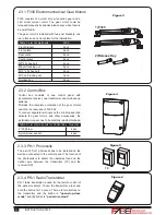
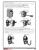
3.3.6 PH-1 Photocells
1). Decide the installation position of the photocells. See
Figure 3.3.6 (1)
.
2). Unscrew the screws and secure the photocells on the post A, B or C. See
Figure 3.3.6 (2)
and
(3)
.
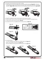
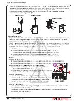
5). Connect the four wires of the light and the antenna to the PCB terminals and place the wires into the conduit if
necessary. See
Figure 3.3.5 (5)
.
6). Tighten the four screws back on the light base.
Figure 3.3.5 (6)
7). Replacing the bulb set. See
Figure 3.3.5 (7)
7.1) Unscrew the flashing light wires from the PCB terminals and make sure the power of the light is off.
7.2) Release the three screws (A)
、
(B)
、
(C) of the flashing light cover.
7.3) Separate the flashing light cover and replace the bulb set with a new one.
7.4) Tighten the three screws (A)
、
(B)
、
(C) of the flashing light cover.
Figure 3.3.5 (5)
Figure 3.3.5 (6)
Figure 3.3.5 (7)
Figure 3.3.6 (1)
Figure 3.3.6 (2)
Figure 3.3.6 (3)
A
B
C
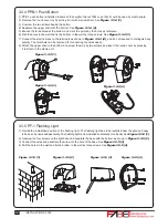
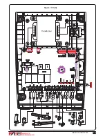
3). Wiring connection:
TX: Connect terminals 1 and 2 on the transmitter with the terminals GND and 24V on the PC200 PCB.
RX: Connect terminals 1, 2 and 4 on the receiver with the terminals GND, 24V and phot1 on the
PC200 PCB. And use an extra wire to connect terminals 2 and 5 on the receiver as a bridge.
See Figure 3.3.6 (4) Figure 3.3.6 (5) and Figure 3.3.8 (5)
Figure 3.3.6 (4)
Figure 3.3.6 (5)
CA
CC
NA: Normal Open
NC: Normal Close
: DC(+) Input Voltage
: DC(-) Input Voltage
C: Common
CA: AC(12~24)
CC: DC(12~24)
VERT:Vertical
ORIZ:Horizontal
O
R
I
Z
NA
NC
C
1
2
3
4
5
Power LED: Green
Transmitter
Vertical Adjustment
Horizontal Adjustment
LED:Red(Beam Alignment)
CA
CC
NA
NC
C
1
2
3
4
5
O
R
I
Z
V
E
R
T
Receiver
CA
CC
NA
NC
C
1
2
3
4
5
O
R
I
Z
V
E
R
T
A
B
C
Summary of Contents for F330
Page 2: ......
Page 19: ...INSTRUCTIONS F330 17 Transformer Figure 3 3 8 5 12V 12V 12V ...
Page 28: ......


